
Installation guide


Digital Monitoring Products XRSuper6/XR20/XR40 Installation Guide
iv
REVISIONS
XRSuper6/XR20/XR40 Installation Guide Digital Monitoring Products
1
INTRODUCTION
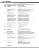
Revisions to This Document
This section explains the changes that were made to this document during this revision. This section lists
the date the change was made, the section number and heading, and a quick summary of the change.
Date Section Number and Heading Summary of Changes
8/06 3.5 Wiring Diagram Added SIA CP-01 information.
6.1 Battery Terminals 3 & 4 Added gure and text to clarify use of battery harnesses
and PTC. Note: Subsequent gure numbers changed.
6.7 Standby Battery Calculation Removed obsolete products.
13.1 Telephone RJ Connector Added gure to clarify phone jack wiring operation.
14.1 Reset Jumper J16 Added gure to clarify and revised text.
23.1 through 23.9 Added False Alarm Reduction features to meet SIA CP-01.
Note: Subsequent section numbers changed.
Listings and Approvals Added SIA CP-01 certication.
5/06 17.5 Wireless Arming Mode Added Wireless operation information.
17.6 Wireless Tamper Added Wireless operation information.
17.7 Wireless External Contact Added Wireless operation information.
17.8 Wireless Supervision Time Added Wireless operation information.
18.9 Wireless Arming Mode Added Wireless operation information.
18.10 Wireless Tamper Added Wireless operation information.
18.11 Wireless External contact Added Wireless operation information.
18.12 Wireless Supervision Time Added Wireless operation information.
21.3 Wireless External Contact Added Wireless operation information.
21.4 Wireless External contact Added Wireless operation information.
21.5 Wireless Fire Verication Added Wireless operation information.
23.2 Common Keypad Displays Revised table to reect valid messages and their operation.
2/06 16.5 Wireless External Contact Added Wireless operation information.
16.6 Wireless Supervision Time Added Wireless operation information.
12/05 3.5 Wiring Diagram Added Aqualite keypad models.
6.7 Standby Battery Calculation Added Aqualite keypad models.
9/05 3.5 Wiring Diagram Added 7760 keypad.
6.7 Standby Battery Calculation Added 7760 keypad.
7/05 3.5 Wiring Diagram Added Power Limited terminal information.
6/05 3.5 Wiring Diagram Added UL AA High Line Security information.
17.4 AA High Line Network Security Added UL AA High Line Security information.
19.8 AA High Line Network Security Added UL AA High Line Security Information.
Listings and Approvals Added UL AA High Line Security information.
12/04 Entire Document Added 734 Module and Thinline keypads where applicable.
1.6 Enclosure Specications Added 341 and 342 Enclosure information. Removed 350
Enclosure information.
3.5 Wiring Diagram Updated keypad listing.
4.1 Mounting the Enclosure Added 341 and 342 Enclosure options. Removed 350
Enclosures option.
4.3 Installation Specications Updated wiring text.
6.7 Standby Battery Calculations Revised current draw values, added Thinline keypads, added
734 Module, corrected Total multiplier value.
Back Cover Added Listings and Approvals
3/04 1.6 Enclosure Specications Added 350 Enclosure information
3.5 Wiring Diagram Added resistor part numbers and updated power supervision
relay information.
Sections 3.4 and 6.7 Added keypad models 690F, 790F, and 693.
Added/revised current draw information.
4.1 Mounting the Enclosure Added 350 Enclosure as an option.
24.2 Installation for Derived Revised drawing and added STU connection text.
Channel Burglary