
Installation guide


Digital Monitoring Products XRSuper6/XR20/XR40 Installation Guide
14
COMPLIANCE
XRSuper6/XR20/XR40 Installation Guide Digital Monitoring Products
15
COMPLIANCE
Universal UL Burglary Specications
15.1 Introduction
The programming and installation specications contained in this section must be completed when installing
the XRSuper6/XR20/XR40 in accordance with any of the UL burglary standards. Additional specications may
be required by a particular standard.
15.2 Wiring
All wiring must be in accordance with NEC, ANSI/NFPA 70, UL 681, and UL 611 for all burglary installations.
15.3 Police Station Phone Numbers
The digital dialer telephone number programmed for communication must not be a police station phone
number, unless that phone number is specically provided for that purpose.
15.4 Bypass Reports
The bypass reports must be programmed as YES for all UL burglary applications. See the XRSuper6/XR20/
XR40 Programming Guide (LT-0305).
15.5 System Maintenance
Proper installation and regular maintenance by the installing alarm company and frequent testing by the end
user is essential to ensure continuous satisfactory operation of any alarm system. Offering a maintenance
program and acquainting the user with the correct procedure for use and testing of the system is also the
responsibility of the installing alarm company.
15.6 Cross-Zoning
Zones used for cross zoning must detect the same event and shall not conict with UL 681 or 1641.
15.7 Ground Start
Ground Start phone lines must not be used for UL listed systems.
15.8 UL Listed Receivers
UL has veried operation with the DMP SCS-1 and SCS-1R Security Receivers, Sur-Gard MLR2-E, SG-HLR2-DG,
FBII CP220PB, Osborne-Hoffman Quick-Alert, and Radionics D6500 receivers.
UL 1023 Specications
Household Burglar-Alarm System Units
16.1 Bell Cutoff
The bell cutoff time cannot be less than ve minutes. See the Programming Guide (LT-0305).
16.2 Entry Delay
The maximum entry delay used must not be more than 45 seconds. See the XRSuper6/XR20/XR40
Programming Guide (LT-0305).
16.3 Exit Delay
The maximum exit delay used must not be more than 60 seconds. See the Programming Guide (LT-0305).
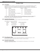
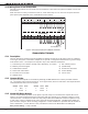
16.4 Zone Expansion on 4-Wire Bus
When expansion zones are used, the keypad and zone expander 4-wire bus must be limited to three feet
in length unless an external communication fail indicator is added. A 12 VDC relay may be wired as a
communication fail indicator. To install, connect the negative side of the indicator to one of the panel’s
annunciator outputs and the positive side to the smoke power (terminal 11 of the panel). See the XRSuper6,
XR20, XR40 Programming Guide (LT-0305).
In addition to the wiring described above, a 24-hour zone must be programmed to activate the appropriate
annunciator output.