
Installation guide


Digital Monitoring Products XRSuper6/XR20/XR40 Installation Guide
4
INTRODUCTION
XRSuper6/XR20/XR40 Installation Guide Digital Monitoring Products
5
INSTALLATION
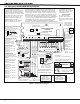
3.5 XRSuper6/XR20/XR40 Wiring Diagram
J4
RED
PROG
J8
XRSuper6/XR20/XR40
Command
Processor™ Panel
J16
Command
Processor Reset
J7
RJ SUP
AC
1
2
3
4 5 6 7
8
10
11 12 13 14
15
16 17 18
19
9
20
21
22 23
24
25
26
+B
BELL
GND
SMK
RED
YE
L
GRN
BL
K
Z1
Z2 Z3 Z4
Z5
Z6
Z7
Z8 Z9
Z10-
AC
-B
GND
GN
D
GND
GND
Z10+
s
s
1k
Ohm
Zone 1
s
s
1k
Ohm
Zone 2
s
s
1k
Ohm
Zone 3
s
s
1k
Ohm
Zone 4
s
s
1k
Ohm
Zone 5
s
s
1k
Ohm
Zone 6
s
s
1k
Ohm
Zone 7
1k Ohm
Zone 8
s
1k Ohm
Zone 9
s
s
Programmer Header J8
Use DMP Model 330 Harness
RJ Cable Monitor J7
Use DMP Model 306 Harness
Phone Jack Connector
See XRSuper6 detail below
Front
Tamper
Plug into
120 VAC 60 Hz
outlet not
controlled by
switch.
16 to 18
gauge
wire
Maximum AC Wire distance
with 16 gauge wire: 70 feet
with 18 gauge wire: 40 feet
RED
BLACK
Cold Water Pipe Earth Ground
Bell
Zone Expander
Model 715
7mA @ 12 VDC
Models 715-8, 715-16
20mA @ 12 VD
C
Smoke
Detector
3.3k Ohm
s
= Supervised Circuit
Smoke Output
100mA @10.4 - 13.2 VDC Terminal 11
22 gauge minimum
22 gauge minimum
22 gauge minimum
22 gauge minimum
RED
YELLOW
GREEN
BLAC
K
Zone Expander
Model 714
7mA @ 12 VDC
Models 714-8, 714-16
20mA @ 12 VD
C
s
s
s
s
s
s
s
Rear
Tampe
r
s
AC Wiring must be in conduit and exit out the
left side of the enclosure.
Wiring on terminals 5 through 26 must exit
right and maintain a 1/4" separation from the
AC and battery positive wiring.
RED
BLAC
K
Use UL Listed Power
Supervision Relay
ra
ted at 12 VDC.
TYPES OF SERVICE
When used with the 350A Enclosure:
suitable for Grade A Local and Police Connect
Mercantile Premises with basic line security,
Grade A Local and Police Connect Mercantile
Safe and Vault with basic line security, Grade B
Central Station and Grade A proprietary. See
sections 17.3, 18.6, 19.2, and 19.5 - 19.7.
Suitable for Household Fire and Grade A
Household Burglary. Test weekly.
Suitable for Grade AA High Line Network
Security
. See sections 17.4 and 19.8.
NFPA 72
This equipment should be installed in accordance with Chapter 2 of the
National Fire Alarm Code, ANSI/NFPA 72-1996, (National Fire Protection
Association, Batterymarch Park, Quincy
, MA 02269). Printed information
describing proper installation, oper
ation, testing, maintenance, evacuation
planning, and repair service is to be provided with this equipment. Warning:
Owner’s instruction notice, not to be removed by anyone except occupant.
HOUSEHOLD FIRE WIRING
UL R
ecognized limited energy
cable must be used for connection
of all initiating, indicating, and
supplementary devices.
POWER LIMITED
All circuits on the Model
XRSuper6, XR20, and XR40
comply with the requirements for
inherent power limitation and are
Class 2
.
Terminals 5-26 are Power Limited.
Minimum voltage on Auxiliary output to
process Sensor trips is 10.2 VDC.
The Class 2, Class 3, and power-limited fire alarm circuits are installed using
CL#, CL3R, or CL3P, or substitute cable permitted by the National Electric
code, ANSI/NFPA 70. The Class 2, Class 3, and power-limited fire alarm
circuit conductors extedning beyond the cable jacket are separ
ated a
minimum of 1/4 in. or by nonconductive tubing or by a nonconductive barrier.
Tamper protection
when required for
Model 350A Attack
Re
sistant Enclosure.
Heat detectors,
manual pull stations,
or any other shorting
device. Unlimited
number of units.
XRSuper6 Zone 6
compatibility
identifier: A
XR20 and XR40
Zone 10
compatibility
identifier: A
Maximum operating
ra
nge:
8.8 VDC - 14.2 VDC.
See the list of approved 2-wire
smoke detectors in Section 11.1 in
the Installation Guide (LT-0624).
UL Listed Resistors
1.0k Ohm - DMP Model 311
3.3k Ohm - DMP Model 309
10K Ohm - DMP Model 308
15
16
17 18
Z3 Z4
Z5
Z6-
GND
Z6+
3.3K EOL
1K EOL 1K EOL
1K EOL
XRSuper6
Detail for XRSuper6
Secondary Power Supply
1.2 Amps maximum
charging current.
Use only 12 VDC rechargeable
batteries. DMP Model 367
.
Replace every 3 to 5 years
.
DMP Transformers
Model 320 – 16.5 VAC 40 VA
Class 2 wire-in.
Model 321 – 16.5 VAC 40 VA
Class 2 plug-in
.
Model 324 – 16.5 VAC 20 VA
Class 2 plug-in.
Household System
A
n alarm sounding device must
be installed indoors so that it is
clearly heard in all sleeping areas.
Keypads
Models 690/690F/790/790F
77mA at 12 VDC Nominal
Model 69
2
70mA at 12 VDC Nominal
Model 693/793
92mA at 12 VDC Nominal
Model 7060
80mA at 12 VDC Nominal
Model 7070
72mA at 12 VDC Nominal
Model 7063
86mA at 12 VDC Nominal
Model 7073
93mA at 12 VDC Nominal
Model 7760
65mA at 12 VDC Nominal
Up to 500mA auxiliary
current at 10.4 to 13.2
VDC from Terminals
7, 11, 25, and 26.
Terminals 5-20
are Power Limited
.
Bell
10.4 - 13.2 VDC Total current:
1.5 Amps max. w/ 40 VA — 600mA w/ 20 VA
Figure 1: System Wiring Diagram