
Installation guide


2 LCD Keypad Installation Guide
LCD Keypad Installation Guide 3
Installing the Keypad
All DMP keypad housings are designed to easily install on any 4” square box,
3-gang switch box, DMP 695 and 696 backbox, or a at surface. Figure 1 shows
the keypad housing base mounting hole locations.
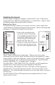
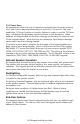
Remove the Cover
The keypad housing is made up of two parts: the front, which contains the
circuit board and keyboard components and the base. Use the following steps
and gures to separate the keypad front and base.
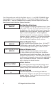
1. Insert a at screwdriver into
one of the slots on the bottom
of the keypad and gently lift the
screwdriver handle toward you
while pulling the halves apart.
Repeat with the other slot.
2. Using your hands, gently separate
the front from the base and set
the front and components aside.
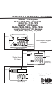
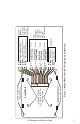
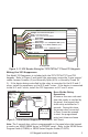
Harness Wiring
Figure 1 shows wiring harness assignments. Observe wire colors when
connecting the red, yellow, green, and black wires to the keypad bus. When
wiring directly to the panel terminals, connect red to panel terminal 7, yellow
to terminal 8, green to 9, and black to panel terminal 10. Use 1k Ohm EOL
resistors, DMP Model 311, on keypad zones 1 through 4.
The 7060/7060A, /7063/7063A/7160/7163, 690/690F, and 693 keypads are
supplied with a 4-wire harness for panel keypad bus connection.
The 7070/7070A, 7073/7073A/7170/7173, 790/790F, and 793 keypads are
supplied with a 12-wire data bus/zone harness. Four wires connect to the
keypad bus. The remaining eight wires are for the four zone inputs: two wires
for each zone.
The 7073/7073A/7173 and 793 keypads are also supplied with one 5-wire
output/reader harness.
Lift screwdriver
handle up
toward you to
separate keypad
cover from base.
Thinline
or Aqualite
Keypad
Building Wall
Lift screwdriver
handle up
toward you to
separate keypad
cover from base.
Building Wall
Security
Command
Keypads