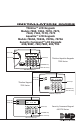
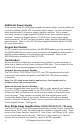
Installation Guide Thinline™ LCD Keypads Models 7060, 7063, 7070, 7073, 7160, 7163, 7170, 7173 Aqualite™ LCD Keypads Models 7060A, 7063A, 7070A, 7073A Security Command™ LCD Keypads 690/690F, 790/790F, 693/793 32-Character Display Power LED ABC PRINTING F R I 2 : 51 AM Armed LED Select Keys 1 2 3 4 5 6 7 8 9 0 CMD Thinline/Aqualite Keypads 7000 Series COMMAND Key Back Arrow Key Data Entry Digit keys 32-Character Display Power LED Armed LED ABC PRINTING F R I 2 : 51 AM Select Keys Thinlin
© 2007 Digital Monitoring Products, Inc. Information furnished by DMP is believed to be accurate and reliable. This information is subject to change without notice.
DMP Keypad Features The DMP Thinline™, Aqualite™, and Security Command™ LCD Keypads offer flexible features and functionality in stylish design choices. Each keypad provides: • Custom 16-character home or business name • Four 2-button Panic keys • AC power LED • Armed LED • 32-character display • Backlit keyboard with easy-to-read lettering • Internal speaker.
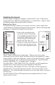
Installing the Keypad All DMP keypad housings are designed to easily install on any 4” square box, 3-gang switch box, DMP 695 and 696 backbox, or a flat surface. Figure 1 shows the keypad housing base mounting hole locations. Remove the Cover The keypad housing is made up of two parts: the front, which contains the circuit board and keyboard components and the base. Use the following steps and figures to separate the keypad front and base.
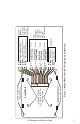
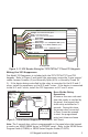
LCD Keypad Installation Guide 3 Red/White White/Red Brown/White – Zone 1 White/Brown 1K EOL 1K EOL Black – Ground Green – Receive Data Yellow – Send Data Red – Keypad Power Orange White – Zone 3 White/Orange 1K EOL All Keypads – Zone 2 Yellow/White – Zone 4 White/Yellow 1K EOL External Reader/ Door Strike 7073/7073A 7173 and 793 Keypads Zones 1 through 4 7070/7070A, 7073/7073A, 7170/7173, 790/790F, and 793 Keypads Green/White – Connect Reader Data 0 White – Connect Reader Data 1 Orange – Door
Additional Power Supply If the current draw for all keypads exceeds the panel output, provide additional current by adding a Model 505-12 auxiliary power supply. Connect all keypad black ground wires to the power supply negative terminal. Run a jumper wire from the power supply negative terminal to the panel common ground terminal. Connect all keypad power (+12 VDC) wires to the power supply positive terminal. Do NOT connect the power supply positive terminal to any panel terminal.
Green/White – Connect Reader Data 0 White – Connect Reader Data 1 Orange – Door Strike Normally Open Gray – Door Strike Common Violet – Door Strike Normally Closed Yellow/White 1K EOL White/Yellow – Orange White 1K EOL White/Orange– Zone 4 Zone 3 Request to Exit (option) Red/White – Zone 2 Door Contact (option) 1K EOL White/Red 1K EOL Brown/White – White/Brown Zone 1 7/0 Panic (option) Black – Ground Green – Receive Data Yellow – Send Data Red – Keypad Power External Card Reader To Keypad Bus Fi
Zone 2 Door Contact with Soft-Shunt™ (7073/7073A/7173, 793 only) If the door being released by the keypad is protected, you can provide a programmed shunt time by connecting its contact to Zone 2 (White/Red pair) on the keypad and enabling the Soft-Shunt feature. See ZONE 2 SHUNT later in this document. Door contacts may be N/C or N/O. Note: The Door Strike time is programmable when the keypad is used on an XR100/XR500 Series, or XR2500F panel.
7/0 Panic Keys All keypads also allow the user to initiate an optional Panic alarm by pressing the 7 and 0 (zero) keys simultaneously for one-half (1/2) second. You must enable the 7/0 Panic function in Installer Options in order to use the 7/0 Panic keys. See Keypad Programming Instructions later in this document. When enabled, all keypads send a Zone Short message to the panel for the first zone of the keypad address.
On all keypads press and hold the Back Arrow (<—) and CMD (COMMAND) keys for two seconds to access User Options. The keypad display changes to SET BRIGHTNESS. Use the COMMAND key to display the next Option or press the Back Arrow to exit the User Options function. < < SET BRIGHTNESS SET TONE Set the keypad LCD Display brightness level, Power and Armed LEDs, and the Green keyboard and logo backlighting.
Entering Alpha Characters To enter an alpha character, press the key that has the desired letter written below it. The keypad display shows the number on that key. To change the number to a letter, press the top row Select key that corresponds to the letter location under the key. For example, if you press key number 1, the letters for that key are A, B, and C. Press the first Select key for A, the second Select key for B, the third Select key for C, and the fourth Select key for special characters.
The Keypad Options menu allows you to set the keypad address, select Supervised or Unsupervised mode, change the default keypad message, selectively enable the 2-button Panic keys, Soft-Shunt, Request-to-Exit, and set entry card options. Note: All programming options display on all keypads, however, actual operation for some programming options is restricted to the listed keypads.
DEFAULT KEYPAD MSG: Default Keypad Message ARM PANIC KEYS: *PN *EM *FI Arm Panic Keys 7/0 PANIC ENABLE: 7/0 Panic Enter a custom message of up to 16 characters to appear on the keypad display top line whenever that line is not used for any other purpose. Press any Select key to clear the current message and use the data entry keys to enter a new custom display. Use this option to configure the top row Select keys as 2-button Panic keys.
Zone 2 Soft-Shunt Time ZONE 2 SOFTSHUNT TIME: 40 (7073/7073A/7173, 793 only) Enter the number of Soft-Shunt seconds to elapse before the Soft-Shunt timer expires. Range is from 20 to 250 seconds. Press any top row select key to enter the number of seconds. Once the door strike relay is activated, the user has 5 seconds to open the door connected to zone 2. The zone is then shunted for the programmed time or until the contact restores to normal.
ACTIVATE ZONE 3 EXIT: NO YES Zone 3 Exit (7073/7073A/7173, 793 only) ZN 3 REX STRIKE TIME: Zone 3 REX Strike Time ALL?: DELAY: 5 NO YES 2 Select YES to enable the Request to Exit feature on zone 3. When zone 3 shorts, the keypad relay activates. During this time, the user can open the protected door to start the programmed Soft-Shunt entry/exit timer. If the door is not opened within the time programmed in the Zone 3 REX Strike Time, the relay restores the door to its locked state.
WIEGAND CODE LENGTH: Custom Card Definitions 45 (7063/7063A, 7073/7073A/7163/7173, 693/793 only) When using a custom credential, enter the total number of bits to be received in Wiegand code including parity bits. Press any top row Select key to enter a number between 0-255 to equal the number of bits. Default is 45 bits. Typically, an access card contains data bits for a site code, a user code, and start/stop/parity bits.
USER CODE POSITION: User Code Position (7063/7063A, 7073/7073A/7163/7173, 693/793 only) 1 When using a custom credential, define the User Code start bit position. Press any Select key to enter a number between 0-255. Default is 1. Press COMMAND to save the entry. USER CODE LENGTH: User Code Length 45 (7063/7063A, 7073/7073A/7163/7173, 693/793 only) When using a custom credential, define the number of User Code bits. Press the fourth Select key to enter a custom number.
Site Codes 5-8 SITE CODES 5-8 > > > > (7063/7063A, 7073/7073A/7163/7173, 693/793 only) Enter site codes 5-8 (left to right separated by > sign). Press the Select key below the > sign to add, delete, or change the site code and press COMMAND. Site code range is 0-999. NO OF USER CODE DIGITS: 5 Number of User Code Digits (7063/7063A, 7073/7073A/7163/7173, 693/793 only) The keypad recognizes user codes from four to six digits in length.
Degraded Mode DEGRADED MODE RELAY ALWAYS OFF (7063/7063A, 7073/7073A/7163/7173, 693/793 only) This option defines the relay action when communication with the panel has not occurred for five seconds. Press any top row Select key to display CHOOSE ACTION. The default is Relay Always Off. CHOOSE ACTION OFF SITE ANY ON Choose the Degraded Mode Action required. Press the first Select key to choose OFF [Default] (Relay Always Off) — The relay does not turn on when any Wiegand string is received.
Accessing Keypad Diagnostics If necessary, refer to Access the Installer Menu earlier in this document. Keypad Diagnostics (KPD DIAG) KPD KPD OPT DIAG STOP The Keypad Diagnostic option allows you to check the display segments, keyboard backlighting and test individual keys. Press the Select key under KPD DIAG. The keypad lights all display segments and illuminates the keyboard in Red. In approximately one second the display backlighting changes to Green.
Additional Programming 7063/7063A, 7073/7073A/7163/7173, and 693/793 Keypads The 7063/7063A, 7073/7073A/7163/7173, and 693/793 keypads allow users to present a proximity credential to the built-in proximity reader located in the keypad backlit logo area. Users can also manually enter their user code into the keypad. The keypad verifies the user code and its authority with the panel. Additionally, the 7073/7073A/7173 or 793 activate the on-board Form C relay releasing a door strike or magnetic lock.
User’s Guide This User’s Guide covers 7063/7063A, 7073/7073A/7163/7173, and 693/793 keypads and contains three different sections: Keypad Arming and Disarming, Keypad Door Strike, and Keypad Entry Delay. All of the examples displayed assume that CLOSING CODE is YES in panel programming. Note: Figures 9 through 12 show the user presenting their card to the keypad. When an external reader is connected to a 7073/7073A/7173 or 793 keypad, the user presents their card to the reader rather than to the keypad.
Home/Away System Arming and Disarming Present your card to the reader. If the system is armed, once the card is validated, all areas are disarmed and the keypad displays ALL SYSTEM OFF. If the system is disarmed when you present your card, once the card is validated, HOME SLEEP AWAY displays. The user can manually select HOME, SLEEP, AWAY or after a short timeout, all areas automatically arm in the AWAY mode.
FCC Information This device complies with Part 15 of the FCC Rules. Operation is subject to the following two conditions: (1) This device may not cause harmful interference, and (2) this device must accept any interference received, including interference that may cause undesired operation. Changes or modifications made by the user and not expressly approved by the party responsible for compliance could void the user’s authority to operate the equipment.
Wiring Specifications When planning a keypad bus installation, keep in mind the following specifications: 1. DMP recommends using 18 or 22-gauge unshielded wire for all keypad and LX-Bus circuits. Do Not use twisted pair or shielded wire for LX-Bus and keypad bus data circuits. To maintain auxiliary power integrity when using 22-gauge wire do not exceed 500 feet. When using 18-gauge wire do not exceed 1,000 feet. Install an additional power supply to increase the wire length or add devices. 2.
24 100mA 87mA + 2mA per active zone 100mA + 2mA per active zone 84mA 84mA + 2mA per active zone 120mA + 2mA per active zone 120mA + 2mA per active zone 85mA 72mA + 1.6mA per active zone 85mA + 1.6mA per active zone 77mA 77mA + 1.6mA per active zone 92mA + 1.6mA per active zone 92mA + 1.
Specifications Operating Voltage 12 VDC Thinline/Aqualite Dimensions 7” W x 5.25” H x 0.5” D Security Command Dimensions 6.5” W x 5” H x 1” D Compatibility All keypads are compatible with all DMP Command Processor™ panels.
Keypad Shortcut Keys Your LCD keypad provides one-button shortcut keys. Holding down a keypad button for two seconds until the tone re-sounds allows you to arm, monitor or reset your system. These options can still be accessed through the User Menu if desired.