
Installation guide


1101 Installation Guide Digital Monitoring Products
3
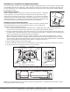
Installing the Transmitter without the Mounting Bracket
These instructions cover installing the transmitter using the base housing without the mounting bracket. If the
installationrequiresthemountingbracket,refertoInstallingtheOptionalMountingBracketabove.
1. Remove the battery if installed.
2.Holdthetransmitterbaseinplacewiththereedswitchnearesttotheareawhereyouplantomountthe
magnet.
3.PlaceonesuppliedscrewintothemountingholelocationasshowninFigure5orusedouble-sidedtapeand
secure the housing to the surface.
4. Place the magnet housing base on the surface nearest to one of the internal reed switch locations and use the
provided screws or double-sided tape to secure the magnet mounting base in place. See Figure 2.
5. If needed, place the magnet mounting spacer below the magnet housing base, align the holes, and use the
provided screws or double-sided tape to secure the base and spacer in place.
6. Spring must be in place on tamper switch for normal
operation.
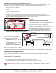
Internal and External Contact Mounting
When connecting an external contact to the terminal
block,DMPrecommendsusing18or22-gaugeunshielded
wire. Do not use twisted pair or shielded wire.
Connecttheexternalcontactasnormallyopen(N/O)or
normally closed (N/C) without any end-of-line resistor.
RefertotheContactoptionunderZoneInformation
in the XR500 Series Programming Guide (LT-0679),
the XR100 Series Programming Guide (LT-0896) or the
XRSuper6/XR20/XR40ProgrammingGuide(LT-0305).
Note: When using both contacts, you
must use consecutive zone numbers.
Refer to the following examples:
• XR500 system—zones562and563
orzones893and894
• XR100 system—zones523and524
orzones593and594
• XRSuper6, XR20, or XR40 system —
zones31and32orzones34and41
Note: For UL listed installations, program
theexternalcontactasNormallyClosed(N/C).SeeZoneProgrammingintheXR500SeriesProgrammingGuide
(LT-0679),theXR100SeriesProgrammingGuide(LT-0896)ortheXRSuper6,XR20,XR40ProgrammingGuide(LT-0305).
Installing or Replacing the Battery
Observepolaritywheninstallingthebattery.Useonly3.0Vlithiumbatteries,DMPModelCR123,ortheequivalent
batteryfromalocalretailoutlet.ForULinstallations,onlyuseCR123AbatteriesmanufacturedbyTekcell.
Note: When setting up a wireless system, it is recommended to program zones and connect the receiver before
installing batteries in the transmitters.
1. If installed, remove the transmitter housing cover.
2. If replacing the battery, remove the old battery and dispose of it properly.
3.Placethe3.0VlithiumbatteryintheholderasshowninFigure5andpressintoplace.
4.LinethetransmittercoversotheDMPlogoisoverthebatteryandsnapthecoverbackintoplace.
Caution:Riskofre,explosion,andburns.Donotrecharge,disassemble,heatabove212°F(100°C),or
incinerate. Properly dispose of unused batteries.
InternalContactMagneticReed Switches
External Contact Terminal Block
Y2
U4
J4 Terminal
Block
Ta mper
Switch
S1
J1
Antenna
Mounting
Block
J2
Battery
Mounting
Location
D1 LED and Lens
Antenna
Transmitter PCB
R14 Reed Switch
R7 Reed Switch
MountingHole
Transmitter Base
Red LED (Survey)
Figure 5: Internal and External Contact Points
Y2
U4
J4 Terminal
Block
S1
Tamper
Switch
J1
Antenna
Mounting
Block
J2
Battery
Mounting
Location
D1 LED and Lens
Antenna
Transmitter PCB
R14 Reed Switch
R7 Reed Switch
Magnet
Magnet
1101 Universal
Transmitter
External
Contact
Magnet
External Contact
Terminal Block
Internal Contact
Reed Switches
Internal Contact
External Contact
Program External
Contact as next
consecutive Zone
Program Internal
Contact as one Zone
Window
Door
1101
Transmitter
Figure 6: External Contact Wiring
www.BevanSecurity.Com