
Installation guide

Digital Monitoring Products XRSuper6/XR20/XR40 Installation Guide
2
INTRODUCTION
Introduction
2.1 Description
The DMP XRSuper6/XR20/XR40 Command Processor™ panels are powerful 12 VDC burglary and Þ re
communicator panels with battery backup. The XR20 and XR40 panels provide nine on-board burglary zones
and one on-board 12 VDC Class B powered Þ re zone. The XRSuper6 provides Þ ve burglary zones and one Þ re
zone. The Þ re zone has a reset capability to provide for 2-wire smoke detectors, relays, or other latching
devices. The panels can communicate to one or two DMP SCS-1/SCS-1R Receivers using SDLC digital dialer,
4-2, or Contact ID (CID) reporting formats. In addition, the XRSuper6/XR20/XR40 can communicate using the
Radionics Modem IIe format.
2.2 System ConÞ gurations
The panels can be programmed to operate as either an All/Perimeter system that provides one Perimeter
area and one Interior area, or as a Home/Sleep/Away system that provides one Perimeter, one Interior, and
one Bedroom area. The Bedroom area can include any protection devices the user wants disarmed during
their sleeping hours and armed in the Away mode. In addition, the XR20/XR40 can operate as a four area
system.
2.3 Before You Begin
Before installing the panel, we recommend you read through the entire contents of this guide. Familiarize
yourself with the features of the panel and the key points to remember during the installation. Be sure to
read and understand all of the caution statements printed in bold italics. In addition to this installation
guide, you should also read through and familiarize yourself with these other product documents:
• XRSuper6/XR20/XR40 Programming Guide (LT-0305) • XR20 Security Command User’s Guide (LT-0303)
• XRSuper6 Programming Sheet (LT-0621) • XR40 Programming Sheet (LT-0493)
• XRSuper6 Security Command User’s Guide (LT-0622) • XR40 Security Command User’s Guide (LT-0494)
• XR20 Program Information Sheet (LT-0302)
2.4 About this Guide
The information contained in this guide is organized into Þ ve sections:
• The Table of Contents at the front of this guide lists all of the headings and the page number where
the information can be found.
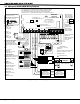
• The Introduction section gives you an overview of the various components that go into a
panel system and diagrams some typical system conÞ gurations.
• The Installation section begins with mounting instructions for the enclosure and takes you through the
proper way to power up the panel prior to programming.
• The Compliance section lists various standards to which the panels comply.
• The Wiring Diagram section provides common system drawings for the panels.
Caution notes
Throughout this guide you will see caution notes containing information you need to know when installing
the panel. These cautions are indicated with a yield sign. Whenever you see a caution note, make sure you
completely read and understand its information. Failing to follow the caution note can cause damage to the
equipment or improper operation of one or more components in the system. See the example shown below.
Always ground the panel before applying power to any devices: The panel must be properly grounded
before connecting any devices or applying power to the panel. Proper grounding protects against
Electrostatic Discharge (ESD) that can damage system components.
2.5 How to Use this Guide
To locate information about the installation of the panel, Þ rst go to the Table of Contents at the front of
this guide. Find the subject heading that closely describes the information you need and turn to the section
number shown to the right of the heading.
The text that follows the heading has been written to provide as much information about the subject as
possible. If you cannot Þ nd the information you need under that heading, try scanning through a few of the
headings before and after and reading the text under those that sound similar.