
Installation guide

Digital Monitoring Products XRSuper6/XR20/XR40 Installation Guide
iv
REVISIONS
Revisions to This Document
This section explains the changes that were made to this document during this revision. This section lists
the date the change was made, the section number and section heading, and a quick summary of the
change.
Date Section Number and Heading Quick Explanation of Changes
2/04 1.6 Enclosure SpeciÞ cations Added 350 Enclosure information
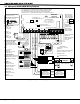
3.5 Wiring Diagram Added resistor part numbers and updated power supervision
relay information.
Sections 3.4 and 6.7 Added keypad models 690F, 790F, and 693.
Added/revised current draw information.
4.1 Mounting the Enclosure Added 350 Enclosure as an option.
24.2 Installation for Derived Revised drawing and added STU connection text.
Chanel Burglary
5/03 6.5 Battery Supervision Information added clarifying the battery test.
6.7 Standby Battery Calculations Current draw of some products adjusted.
8.7 Keypad Addressing Section added with table explaining keypad addressing.
1/03 1.4 Keypads Added eight and 16-zone expansion modules.
1.6 Enclosure SpeciÞ cations Updated enclosure speciÞ cations.
3.4 Command Processor Accessories Added 690 keypad.
3.5 XRSuper6/XR20/XR40 Wiring Updated current draw ratings.
4.1 Mounting the Enclosure Updated enclosure illustrations.
4.3 Installation SpeciÞ cations Updated wording for bus circuit distances.
11.1 Terminals 25 and 26 Added note about sensor reset on zone 10. Smoke Detector
Chart updated.
11.2 Zone 9 Wiring on XR20/XR40 Section added about proper EOL wiring on zone 9.
12.3 Model 860 Relay Module Updated relay contact rating to one Amp.
15.8 UL Listed Receivers Added MLR2-E Receiver.
20.8 UL Listed Receivers Added MLR2-E Receiver.
24.2 Installation for Derived Channel Updated PCB illustration and added note about zone type.
Back Cover Added Operating Instructions