
Installation guide

XRSuper6/XR20/XR40 Installation Guide Digital Monitoring Products
19
WIRING DIAGRAMS
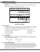
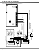
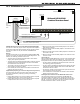
24.2 Installation for Derived Channel Burglary
= Supervised Circuit
S
1 2 3 4 5 6
Panel Auxiliary Power - Terminal 7
Note 1
Note 1
RJ31X
Telco Jack
Panel Common - Terminal 10
Supervisory Zone Input - Terminal 13
J16
Command Processor Reset
AC
12 3 4 5
6
78
10
11
12 13 14 15 16
17
18
19
9
20
21
22 23 24 25 26 27 28
AC +B -B BELL GND SM K G NDRED YEL GRN BLK Z1 Z2GND GND GND GNDZ3 Z4 Z5 Z6 Z7 Z8 Z9 + Z9 - Z10 + Z10 -
Phone Jack
Connector
J4
XRSuper6/XR20/XR40
Command Processor Panel
S S
S
Note 1: Use EOL Termination Assembly P/N
21024-0001 (2.2k Ohm 1/2 W Resistor).
Use EOL Termination
Assembly P/N 21024-0003
(590 Ohm 1/2 W Resistor)
DCX Systems
STU-2Z
Program Zone 1
(terminal 12)
as a
Supervisory
Zone
1
2
3
4
J11
INTERFACING STU-2Z/STU-4Z TO THE XRSuper6/XR20/XR40 PANELS
The STU-2Z or STU-4Z may only be used in conjunction with telephone
systems that support DCX Systems Derived Channel multiplex network.
The STU-2Z or STU-4Z can only be installed in a DMP Model 350
enclosure.
Burglary
The STU-2Z and STU-4Z are cross listed with the XRSuper6/XR20/XR50
panels as an accessory for Grade AA Central Station Burglar Alarm. For
Grade AA, the following conditions must be met:
• The panel must be installed and programmed to meet Grade A
burglary alarm system requirements.
• The panel must be installed and programmed for reporting all alarm
conditions through the integral DACT to the same central station
that monitors the STU-2Z or STU-4Z.
• The STU-2Z or STU-4Z must be mounted in the panel enclosure and
wired according to Section 32.4 above.
• Once installed, the central station must enable 2-minute off-hook
polling of the STU-2Z or STU-4Z.
Supplementary Reporting (
for Commercial Burglar Alarm Applications)
The two zones of the STU-2Z or the four zones of the STU-4Z may
be used for supplementary reporting by meeting the following
requirements.
1. Program Relay Output #1 for all alarm conditions that are required
to report alarm on Zone 1 of the STU-2Z or STU-4Z.
2. Program Relay Output #2 for all alarm conditions that are required
to report alarm on Zone 2 of the STU-2Z or STU-4Z.
3. Wire the normally-open terminals of Relay Output #1 to Terminal 1
of the STU-2Z or STU-4Z.
4. Wire the common terminal of Relay Output #1 to Terminal 2 of the
STU-2Z or STU-4Z.
5. Wire the normally-open terminal of Relay Output #2 to Terminal 3 of
the STU-2Z or STU-4Z.
6. Wire the common terminal of Relay Output #2 to Terminal 2 of the
STU-2Z or STU-4Z.
Commercial Fire
When the XRSuper6/XR20/XR40 panel is used as a Central Station Alarm
Commercial Fire System with one telephone line, in conjunction with
DCX Systems STU-2Z or STU-4Z, the following conditions must be met:
• The panel must be installed and programmed to meet commercial
Þ re (reporting) systems requirements.
• The panel must be installed and programmed for reporting all alarm
conditions and trouble conditions to the same central station that
monitors the STU-2Z or STU-4Z.
• The STU-2Z or STU-4Z must be mounted in the panel enclosure and
wired according to Section 32.4 above.
• Once installed, the central station must enable 2-minute off-hook
polling of the STU-2Z or STU-4Z.
Installing the STU-2Z/STU-4Z into the DMP Model 350 Enclosure
The STU board is mounted in the left side of the DMP Model 350
enclosure by slipping the optional corner mounting bracket over the
edge of the enclosure. Use DCX Part # 27074-002 (2Z) or Part # 27078-
001 (4Z). Connect the STU power wires and telco cables to the panel
terminals and RJ31X as shown in Section 24.2 above.