
Installation guide

Digital Monitoring Products XRSuper6/XR20/XR40 Installation Guide
18
WIRING DIAGRAMS
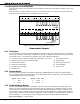
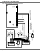
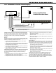
24.1 Multiple Indicating Circuit Module Installation
S
AUXILIARY
POWER
SUPPLY
12 or 24 VDC
5 Amp Maximum
Power Supply
Trouble Contacts
N/C
NOTE: If an auxiliary supply is not used,
terminals 3 and 4 on the 866 Indicating
Circuit Module can be jumpered together
to supply bell power from the XR20 panel.
A maximum of 1.5 Amps at 12 VDC is
available from terminal 5 of the XRSuper6.
Each 866 Indicating Circuit Module
in alarm draws up to 35mA from its
terminal 3 alarm input.
AC
1
23 4
5678
10 11 12 13 14
15 16 17 18 19
AC +B -B BELL GND SMK
GND
9
RED YEL
GRN
BLK
GND GND
The Auxiliary Power Supply and Indicating Circuit Module
trouble contact zone must be programmed as a Supervisory
Type zone and must be selected for display in the keypad
status list.
= Supervised Circuit
S
S
S
S
S
1
2
3
4
5
6
7
8
Auxiliary Power
Ground
Alarm Input
Bell Power + Input
Bell Power Ð Input
Bell A + Output -
Bell A Ð Output
Bell B + Output
Bell T rouble
Bell T rouble
Bell B Ð Output
9
10
11
UL Listed, Polarized
Indicating Devices.
Style Z
Notification Circuit Module
DMP Model 865
85mA at 12 VDC
AUXILIARY
POWER
SUPPLY
Power Supply
Trouble Contacts
N/C
12 or 24 VDC
5 Amp Maximum
S
S
1
2
3
4
5
6
7
8
Auxiliary Power
Ground
Alarm Input
Bell Power Input
Bell Output +
Bell Output -
Bell T rouble
Bell T rouble
UL Listed, Polarized
notification Devices.
10k W EOL Resistor
DMP Model 308
Notification Circuit Module
DMP Model 866
37mA at 12 VDC
1k W
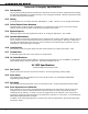
Optional Module installation
Each 865 Notification Circuit Module
in alarm draws up to 85mA from its
terminal 3 alarm input.
S
S
S
S
S
S
S
S
S
S
Style W
J16
Command Processor Reset
Phone Jack Connector
EPROM Socket
U11
J11
1
2
3
4
J4
Z1
Z2
Z3
Z4
Z5
Z6+
Z6-