
Installation guide

XRSuper6/XR20/XR40 Installation Guide Digital Monitoring Products
13
INSTALLATION
Telephone RJ Connector
13.1 Description
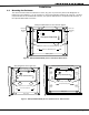
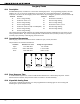
Connect the panel to the public telephone network by installing a DMP 356 RJ Cable between the panel’s J4
connector and the RJ31X or RJ38X phone jack.
A two pin header labeled RJ SUP (J7) is provided to allow monitoring of the telephone cable connected
between the panel and a RJ38X jack (pins 2 and 7 jumpered). Attach a DMP Model 306 Harness between J7
and any available zone. The pins of J7 are connected via the telephone cable to 2 and 7 of the RJ38X jack.
The RJ38X jack provides a jumper between pins 2 and 7 which completes the circuit.
When the zone is programmed for a Supervisory type (SV) and the telephone cable is removed, the keypad
displays the zone in trouble and produces a steady tone.
13.2 FCC Registration
The panel complies with FCC part 68 and is registered with the FCC.
Registration number: CCKUSA - 18660 - AL - R
Ringer Equivalence: 1.1B
13.3 NotiÞ cation
Registered terminal equipment must not be repaired by the user. In case of trouble, the device must be
immediately unplugged from the telephone jack. The factory warranty provides for repairs. Registered
terminal equipment may not be used on party lines or in connection with coin telephones. No tiÞ cation must
be given to the telephone company with the following information:
a. The particular line(s) the service is connected to
b. The FCC registration number
c. The ringer equivalence
d. The make, model, and serial number of the device
13.4 Ground Start
To conÞ gure the panel for ground start operation, you must install the appropriate ground start module and
program one of the panel’s available annunciator outputs for Ground Start operation. Refer to the panel
Programming Guide for complete programming information. This option must not be selected on a UL listed
system.
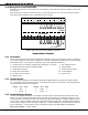
Reset Jumper J16
14.1 Description
There are two reset jumpers located at the top right of the panel’s circuit board labeled RESET.
Momentarily shorting these jumpers allows you to reset the microprocessor. Resetting the panel allows you
to enter the panel’s internal programmer.
To reset the panel when Þ rst installing the system, place the blade of a slotted screwdriver across the two
reset jumpers after applying power to the panel.
To reset the panel while the system is operational (for example, prior to reprogramming), you can short the
jumpers without powering down the system.
After resetting the panel for programming, you must begin within 30 minutes. If you wait longer than 30
minutes, you will have to reset the panel again.