
Installation guide

Digital Monitoring Products XRSuper6/XR20/XR40 Installation Guide
12
INSTALLATION
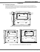
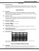
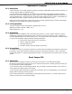
11.2 Wiring Zone 10 on XR20/XR40
The end-of-line resistor for zone 9 must not be accidentally connected to the positive terminal of zone 10 as
shown below.
When zone 9 is incorrectly connected to zone 10, a false alarm may occur on zone 2 of the panel when the
panel picks up the telephone line to communicate to the receiver.
AC
1
2
3
4567
8
10
11 12 13 14
15
16 17 18
19
9
20
21
22 23
24
25
26
+B
BELL
GND
SMK
RED
YEL
GRN
BLK
Z1
Z2 Z3 Z4
Z5
Z6
Z7
Z8 Z9
Z10-
AC
-B
GND
GND
GND
GND
Z10+
1K EOL 1K EOL 1K EOL 1K EOL 1K EOL 1K EOL 1K EOL 1K EOL
1K EOL
1K EOL
Zone 9 is correctly sharing the ground
terminal with zones 7 and 8.
Correct Wiring
AC
1
2
3
4567
8
10
11 12 13 14
15
16 17 18
19
9
20
21
22 23
24
25
26
+B
BELL
GND
SMK
RED
YEL
GRN
BLK
Z1
Z2 Z3 Z4
Z5
Z6
Z7
Z8 Z9
Z10-
AC
-B
GND
GND
GND
GND
Z10+
1K EOL 1K EOL 1K EOL 1K EOL 1K EOL 1K EOL 1K EOL 1K EOL 1K EOL 1K EOL
Zone 9 is incorrectly
connected to zone 10.
Incorrect Wiring
Figure 5: Zone 9 and 10 End-of-Line Resistor Placement
Annunciator Outputs
12.1 Description
The four annunciator outputs can be programmed to indicate the activity of the panel’s zones or conditions
occurring on the system. Annunciator outputs do not provide a voltage but instead switch-to-ground voltage
from another source. The outputs can respond to any of the conditions listed below:
1) Activation by zone condition: Steady, Pulse, Momentary, or Follower 7) Exit and Entry timers
2) Manually from the Security Command keypad 8) System Ready
3) Communication failure 9) Ground start activation
4) Armed area annunciation 10) Cellular Backup
5) Fire Alarm or Fire Trouble 11) Late to Close
6) Ambush alarm
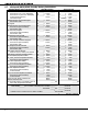
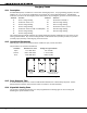
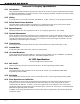
12.2 Harness Wiring
The open collector outputs are accessible by installing the DMP 300 Harness on the 4-pin header labeled
J11. The output locations are shown below. For UL applications, devices connected to the outputs must be
located within the same room as the panel.
Output Color Wire Output Color Wire
1 Red 1 3 Green 3
2 Yellow 2 4 Black 4
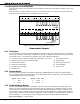
12.3 Model 860 Relay Module
Connect a Model 860 Relay Module to the panel to provide relays for the annunciator outputs that can be
used for electrical isolation between the alarm panel and other systems or for switching voltage to control
various functions. The module includes one relay and provides three additional sockets for expansion of up
to four relays. Power is supplied to the relay coils from the panel’s keypad bus. The 860 mounts inside the
panel enclosure using the 3-hole mounting conÞ guration. Plastic standoffs are provided with the module for
ease of installation. A 4-wire harness is also provided that connects the Model 860 to the DMP panel.
Relay Contact Rating: 1 Amp at 30 VDC