
Installation guide

Digital Monitoring Products XRSuper6/XR20/XR40 Installation Guide
6
INSTALLATION
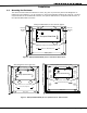
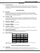
4.2 Mounting Keypads
Security Command keypads have removable covers that allow you to easily mount the base to a wall or other
ß at surface using the screw holes provided on each corner.
For mounting keypads on solid walls, or for applications where conduit is required, use a DMP 695, 696, 775,
or 776 keypad conduit backbox.
4.3 Installation SpeciÞ cations
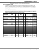
Several factors determine the performance characteristics of the keypad bus: the length of wire used, the
number of devices connected, and the voltage at each device. When planning an LX-Bus™ and keypad bus
installation, keep in mind the following four speciÞ cations:
1. You can install individual keypads on wire runs of up to 500 feet using 22 gauge wire or up to 1,000 feet
using 18 gauge wire. To increase the wire length or add additional devices, a power supply is required.
2. Maximum distance for any one keypad bus circuit (length of wire) is 2,500 feet regardless of the gauge
of wire. This distance can be in the form of one long wire run or multiple branches with all wiring
totaling no more than 2,500 feet.
3. Maximum number of devices per 2,500 feet circuit is 40. (Note: Each panel allows a speciÞ c number
of supervised keypads. Additional keypads can be added in the unsupervised mode. Refer to the
panel’s installation guide for the speciÞ c number of supervised keypads that are allowed.)
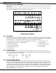
4. Maximum voltage drop between the panel (or auxiliary power supply) and any device is 2.0 VDC. If the
voltage at any device is less than the required level, an auxiliary power supply should be added at the
end of the circuit. The 2.0 VDC rule has not been tested by UL.
Refer to the 710 Bus Splitter/Repeater Module Installation Sheet (LT-0310) and the Trouble-free LX-Bus and
Keypad Bus Wiring Application Note (LT-2031) for additional information.
Primary Power Supply
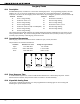
5.1 AC terminals 1 and 2
Connect the transformer wires to terminals 1 and 2 on the panel. Use no more than 70 ft. of 16 gauge, or 40
ft. of 18 gauge, wire between the transformer and the panel.
Always ground the panel before applying power to any devices: The panel must be properly grounded
before connecting any devices or applying power to the panel. Proper grounding protects against
Electrostatic Discharge (ESD) that can damage system components. See Earth ground, in the Secondary
Power Supply section.
5.2 Transformer Types
The transformer for the panel is 16.5 VAC 40 VA, which provides up to 1.5 Amps of bell output current,
500mA of auxiliary current, and 100mA of smoke detector output. You can use either the Model 320 wire-in
or 321 plug-in transformer with the panel. The total current available is limited by the total battery standby
requirements of the installation.
The transformer must be connected to a 120 VAC 60 Hz commercial power outlet that is not con trolled by
a wall switch. Never share the transformer output with any other equipment.