
Installation guide

XRSuper6/XR20/XR40 Installation Guide Digital Monitoring Products
5
INSTALLATION
Installation
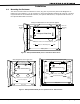
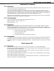
4.1 Mounting the Enclosure
The metal enclosure must be mounted in a secure, dry place to protect the panel from damage due to
tampering or the elements. It is not necessary to remove the PCB when installing the enclosure. The PCB
may be installed in the standard 340 enclosure, the optional 349 enclosure, the optional 350 enclosure, or
the optional 350A Grade A enclosure.
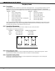
Slide panel PCB between formed metal supports
Dual 1/2" and 3/4" Conduit Knockouts
Battery Shelf
Enclosure Mounting Holes
Enclosure
Mounting
Hole
Enclosure
Mounting
Hole
Phone Jack
Connector
J4
Command Processor
Reset
J16
J11
1
2
3
4
XRSuper6/XR20/XR40
Panel
PCB
screw
Panel
PCB
screw
Figure 2: XRSuper6/XR20/XR40 panel in Standard 340 Enclosure
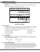
Enclosure Mounting Holes
Enclosure Mounting Holes
3-Hole
Pattern for
Accessory
Modules
3-Hole
Pattern for
Accessory
Modules
3-Hole
Pattern for
Accessory
Modules
3-Hole
Pattern for
Accessory
Modules
3-Hole
Pattern for
Tamper
mounting
Dual 1/2" and 3/4" Conduit Knockouts
Battery Shelf
XRSuper6/XR20/XR40
Phone Jack
Connector
Command Processor
Reset
J16
J4
1
2
3
4
Panel
PCB
screw
Panel
PCB
screw
Enclosure Mounting Holes
Dual 1/2" and 3/4" Conduit Knockout
Battery Shelf
Enclosure Mounting Holes
J1111
XRSuper6/XR20/XR40
Phone Jack
Connector
Command Processor
Reset
J16
J4
J11
1
2
3
4
Enclosure Mounting Holes
Slide panel PCB into lower enclosure slots
Slide panel PCB into lower enclosure slots
Panel
PCB
screw
Panel
PCB
screw
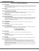
Figure 3: XRSuper6/XR20/XR40 panel in Optional 349 or 350 Enclosure