INSTALLATION GUIDE XRSUPER6 / XR20 / XR40 COMMAND PROCESSOR™ PANELS
MODEL XRSuper6/XR20/XR40 COMMAND PROCESSOR INSTALLATION GUIDE FCC NOTICE This equipment generates and uses radio frequency energy and, if not installed and used properly in strict accordance with the manufacturer’s instructions, may cause interference with radio and television reception.
TABLE OF CONTENTS Revisions to This Document Panel SpeciÞcations 1.1 1.2 1.3 1.4 1.5 1.6 Power Supply .........................................1 Communication.......................................1 Panel Zones............................................1 Keypads .................................................1 Outputs..................................................1 Enclosure SpeciÞcations ..........................1 Introduction 2.1 2.2 2.3 2.4 2.5 Description ......................................
TABLE OF CONTENTS Burglary Zones 10.1 10.2 10.3 10.4 Description ...........................................10 Operational Parameters .........................10 Zone Response Time .............................10 Keyswitch Arming Zone .........................10 Powered Zone for 2-Wire Smoke Detectors 11.1 Terminals 25 and 26..............................11 11.2 Wiring Zone 10 on XR20/XR40 ...................12 Annunciator Outputs 12.1 12.2 12.3 Description ...........................................
TABLE OF CONTENTS UL 365 And 609 SpeciÞcations 19.1 19.2 19.3 19.4 19.5 19.6 19.7 Entry Delay ..........................................15 Grade A Bell .........................................15 Bell Cutoff ............................................15 Automatic Bell Test ...............................15 Grade A Mercantile................................15 Mercantile Safe and Vault ......................15 Line Security for Police Connect .............
REVISIONS Revisions to This Document This section explains the changes that were made to this document during this revision. This section lists the date the change was made, the section number and section heading, and a quick summary of the change. Date Section Number and Heading Quick Explanation of Changes 2/04 1.6 Enclosure SpeciÞcations 3.5 Wiring Diagram Added 350 Enclosure information Added resistor part numbers and updated power supervision relay information.
INTRODUCTION Panel SpeciÞcations 1.1 Power Supply Transformer Input: 16.5 VAC 40 VA (Models 320 Wire-in or 321 Plug-in) Standby Battery: 12 VDC 7.0 Ah (40 VA transformer charges up to 2 batteries) Auxiliary Output: 12 VDC at 500mA Bell Output: 12 VDC at 1.5 Amps Smoke Detector Output: 12 VDC at 100mA All circuits inherent power limited 1.
INTRODUCTION Introduction 2.1 Description The DMP XRSuper6/XR20/XR40 Command Processor™ panels are powerful 12 VDC burglary and Þre communicator panels with battery backup. The XR20 and XR40 panels provide nine on-board burglary zones and one on-board 12 VDC Class B powered Þre zone. The XRSuper6 provides Þve burglary zones and one Þre zone. The Þre zone has a reset capability to provide for 2-wire smoke detectors, relays, or other latching devices.
INTRODUCTION System Components 3.1 Description The DMP system is made up of an alarm panel with built in communicator, an enclosure, a 16.5 VAC transformer, and a 12 VDC 7.0 Ah battery. You can add Security Command keypads to the system and can also connect auxiliary devices to the panel’s open collector outputs to expand the basic system. Combined current requirements of additional modules may require an auxiliary power supply.
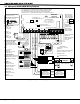
INTRODUCTION 3.5 XRSuper6/XR20/XR40 Wiring Diagram The Class 2, Class 3, and power-limited fire alarm circuits are installed using CL#, CL3R, or CL3P, or substitute cable permitted by the National Electric code, ANSI/NFPA 70. The Class 2, Class 3, and power-limited fire alarm circuit conductors extedning beyond the cable jacket are separated a minimum of 1/4 in. or by nonconductive tubing or by a nonconductive barrier. AC Wiring must be in conduit and exit out the left side of the enclosure.
INSTALLATION Installation 4.1 Mounting the Enclosure The metal enclosure must be mounted in a secure, dry place to protect the panel from damage due to tampering or the elements. It is not necessary to remove the PCB when installing the enclosure. The PCB may be installed in the standard 340 enclosure, the optional 349 enclosure, the optional 350 enclosure, or the optional 350A Grade A enclosure.
INSTALLATION 4.2 Mounting Keypads Security Command keypads have removable covers that allow you to easily mount the base to a wall or other ßat surface using the screw holes provided on each corner. For mounting keypads on solid walls, or for applications where conduit is required, use a DMP 695, 696, 775, or 776 keypad conduit backbox. 4.
INSTALLATION Secondary Power Supply 6.1 Battery Terminals 3 and 4 Connect the black battery lead to terminal 4 on the panel and to the negative terminal of the battery. The negative terminal connects to the enclosure ground internally through the panel circuit board. Connect the red battery lead to terminal 3 on the panel and to the positive terminal of the battery. Observe polarity when connecting the battery. The panel can charge up to two batteries.
INSTALLATION 6.
INSTALLATION Bell Output 7.1 Terminals 5 and 6 Nominal 12 VDC is supplied by terminal 5 on the panel to power alarm bells or horns. The output is rated for a maximum of 1.5 Amps with a 40 VA transformer. This output can be steady, pulsed, or Temporal Code 3 depending upon the Bell Action speciÞed in Output Options programming. Terminal 6 is the ground reference for the bell circuit. Keypad Data Bus 8.1 Description Terminals 7, 8, 9, and 10 of the panel are designated as the keypad data bus.
INSTALLATION Burglary Zones 10.1 Description On XR20/XR40 panels, terminals 12 to 24 are the nine burglary zones. For programming purposes, the zone numbers are 1 to 9. The zone conÞgurations on terminals 12 to 24 are described below. The XRSuper6 terminals 12 to 18 are the Þve burglary zones with terminal 16 providing the ground for zone 5 (terminal 18).
INSTALLATION Powered Zone for 2-Wire Smoke Detectors 11.1 Terminals 25 and 26 A resettable 2-wire Class B powered zone is provided on terminals 25 (positive) and 26 (negative) of the panel. For programming purposes, the zone number is 10 on the XR20/XR40 and zone 6 on the XRSuper6. The zone uses a Model 309, 3.3k Ohm EOL resistor (provided with the panel) and has an operating range of 8.8 to 14.2 VDC. The UL compatibility identiÞer is: A.
INSTALLATION 11.2 Wiring Zone 10 on XR20/XR40 The end-of-line resistor for zone 9 must not be accidentally connected to the positive terminal of zone 10 as shown below. When zone 9 is incorrectly connected to zone 10, a false alarm may occur on zone 2 of the panel when the panel picks up the telephone line to communicate to the receiver.
INSTALLATION Telephone RJ Connector 13.1 Description Connect the panel to the public telephone network by installing a DMP 356 RJ Cable between the panel’s J4 connector and the RJ31X or RJ38X phone jack. A two pin header labeled RJ SUP (J7) is provided to allow monitoring of the telephone cable connected between the panel and a RJ38X jack (pins 2 and 7 jumpered). Attach a DMP Model 306 Harness between J7 and any available zone.
COMPLIANCE Universal UL Burglary SpeciÞcations 15.1 Introduction The programming and installation speciÞcations contained in this section must be completed when installing the XRSuper6/XR20/XR40 in accordance with any of the UL burglary standards. Additional speciÞcations may be required by a particular standard. 15.2 Wiring All wiring must be in accordance with NEC, ANSI/NFPA 70, UL 681, and UL 611 for all burglary installations. 15.
COMPLIANCE UL 1610 and 1076 SpeciÞcations Central-Station and Proprietary Burglar-Alarm Units 17.1 Opening/Closing Reports The Opening/Closing Reports option must be programmed as YES. See the Programming Guide (LT-0305). 17.2 Automatic Bell Test This option must be programmed as YES. See the XRSuper6/XR20/XR40 Programming Guide (LT-0305). 17.3 Proprietary Dialer The Model XRSuper6/XR20/XR40 provides Grade A proprietary service when conÞgured as a digital dialer.
COMPLIANCE 19.7 Line Security for Police Connect Basic line security is provided when the Model XRSuper6/XR20/XR40 is conÞgured as a dialer system. Universal UL And NFPA Fire Alarm SpeciÞcations 20.1 Introduction The programming and installation speciÞcations contained in this section must be completed when installing the Model XRSuper6/XR20/XR40 in accordance with any of the UL or NFPA Þre standards. Additional speciÞcations may be required by a particular standard. 20.
COMPLIANCE Troubleshooting 23.1 Troubleshooting Section This section of the Installation Guide provides troubleshooting information for use when installing or servicing an XRSuper6/XR20/XR40 system. Problem Possible Cause Possible Solutions J16 Jumper is installed. Keypad displays “SERVICE REQUIRED” Keypad display is not functional. When a key is pressed, only a short beep is emitted. Remove the J16 reset jumper.
Digital Monitoring Products 18 1k W Bell T rouble Bell T rouble Bell B Ð Output Bell B + Output Bell A Ð Output 10 11 9 8 7 6 5 Bell A + Output - 4 Bell Power Ð Input 2 3 1 Bell Power + Input Alarm Input Ground Auxiliary Power Power Supply Trouble Contacts N/C AUXILIARY POWER SUPPLY 8 7 6 5 4 3 2 1 S S S S S S S DMP Model 865 85mA at 12 VDC S S S S S S 12 or 24 VDC 5 Amp Maximum Notification Circuit Module 12 or 24 VDC 5 Amp Maximum Bell T rouble Bell T roub
WIRING DIAGRAMS 24.
OPERATING INSTRUCTIONS MODEL XRSuper6/XR20/XR40 PANELS When using Model 692 LED Keypad, please refer to 692 User Guide (LT-0275) NORMAL STANDBY CONDITION When the system is in the normal standby condition, the keypad shows either the time of day/System Ready or a blank display. ALARM CONDITION When the system is in an alarm condition, the keypad keys glow red and the display shows the violated zone name(s) followed by an alarm display. ARMING THE SYSTEM Press the COMMAND key until arming options appear.