
Installation guide

Digital Monitoring Products XR200 Installation Guide
2
INTRODUCTION
XR200 Installation Guide Digital Monitoring Products
3
INTRODUCTION
2.4 Partitions and Areas
The 20 reporting areas of the XR200 are divided into four separate partitions. Partition 1 provides up to eight
individual reporting areas while partitions 2, 3, and 4 each provide up to four individual reporting areas.
Keypads installed on the XR200 system are assigned to partitions allowing users to operate the functions of
those areas.
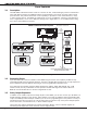
2.5 Central Station Communication
You can program the XR200 panel for one of many communication formats:
• Local annunciation only
• Reporting to one or two DMP SCS-1 Receivers using multiplex, host, or digital dialer
• Reporting to one or two DMP SCS-1R Receivers using host or digital dialer
The panel can also communicate to non-DMP receivers using the Contact ID or Modem IIe communication
formats. The XR200 connects at the premises to a standard RJ31X or RJ38X telephone jack. Use the DMP
893 or 893A Dual Phone Line Module when connecting the XR200 panel to two separate phone lines in re or
burglary applications.
2.6 Before you Begin
Before installing the XR200, we recommend you read through the entire contents of this guide. Familiarize
yourself with the features of the panel and the key points to remember during the installation. Be sure to
read and understand all of the caution statements printed in bold italics.
2.7 About this Guide
The information in this guide is organized into ve sections:
• The Table of Contents at the front lists the headings and subheadings used throughout each section of
the guide. To the right of each heading is the section number where the information can be found.
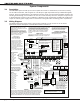
• The Introduction section gives you an overview of the various components that go into a XR200 system
and provides diagrams of typical system congurations.
• The Installation section begins with mounting instructions for the enclosure and continues on to detail
the operational characteristics of the XR200 panel.
• The Compliance section describes the various regulations the XR200 complies with, such as UL.
• The System Diagrams illustrate different ways to wire the XR200 to a variety of modules.
Caution notes
Throughout this guide you will see caution notes containing information you need to know when installing
the XR200 panel. These cautions are written with a bold, italicized introductory clause followed by a
detailed description of the caution. See the example shown below:
Always ground the panel before applying power to any devices: The XR200 must be properly grounded
before connecting any devices or applying power to the panel. Proper grounding protects against
Electrostatic Discharge (ESD) that can damage system components.
Whenever you see a caution note, make sure you completely read and understand its information. Failing
to follow the caution note can cause damage to the equipment or improper operation of one or more
components in the system.
2.8 How to Use This Guide
To locate information about the installation of the XR200, rst go to the Table of Contents at the front of
this guide. Find the subject heading that best describes the information you need and turn to the section
number shown to the right of the heading.
The text that follows the heading has been written to provide as much information about the subject as
possible. If you cannot nd the information you need under that heading, try scanning through a few of the
headings before and after and reading the text under those that sound similar.