
Installation guide

Digital Monitoring Products XR200 Installation Guide
iv
REVISIONS
XR200 Installation Guide Digital Monitoring Products
1
INTRODUCTION
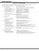
Revisions to This Document
This section explains the changes that were made to this document during this revision. This section lists the date
the change was made, the section number and section heading, and a quick summary of the change.
Date Section Number and Heading Quick Explanation of Changes
12/06 3.2 Wiring Diagram Removed UL Burglary and Access Control text and information.
13.2 Output Harness Wiring Removed UL Burglary and Access Control text and information.
16 Universal UL Burglary Specications Removed entire section. UL listing expired.
17 UL 1023 Specications Removed entire section. UL listing expired.
18 UL 1610 and 1076 Specications Removed entire section. UL listing expired.
19 UL 1635 Specications Removed entire section. UL listing expired.
20 UL 365 and 609 Specications Removed entire section. UL listing expired.
Note: Subsequent section numbers revised.
20.8 Rothenbuhler Install Diagram removed.
20.9 Cell Backup for Derived Chanel Burg Diagram removed.
Note: Subsequent section numbers revised.
3/04 3.2 Wiring Diagram Added UL required text and information.
Section 6.8 Added keypad models 690F, 790F, and 693.
Added/revised current draw information.
25.7 Cellular Backup Installation Revised drawing and added STU connection text.
for Derived Channel Burglary
6/03 FCC Statement Adjusted to properly reect Class A.
Entire Document Added SCS-1R references to the appropriate places.
6.8 Standby Battery Calculations Current Draw on some products adjusted.
10.3 Zone Response Time Changed from 160 milliseconds to 167.
11.1 Terminals 25-26 and 27-28 EOL information claried.
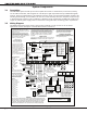
7/02 4.1 Mounting the Enclosure Model 325 Transformer Bracket, Terminal Strip added to Figure 3.
1.7 Enclosure Specications Information added about 349, 350, 350A Enclosures.
11.1 Terminals 25-26 and 27-28 Information added about Sensor Reset’s affect on Zones 9 and 10.
23.7 Local Protective Signaling Systems Information added requiring the 893 to be used in local commercial
re installations
23.10 Fire Protective Signaling Section added with compliance information for the iCOM.
Systems with an iCOM™
10/01 3.4 Accessory Devices New DMP products added to the table.
4.3 Connecting Serial Devices LX-Bus and keypad bus information added.
6.8 XR200 Power Requirements 710F added to the Standby Battery Calculations chart.
11.2 Compatible 2-Wire Smokes Chart updated to include smoke detectors that are compatible with
the 725 zone expander and other 12 VDC smoke detectors.