
Installation guide

Digital Monitoring Products XR200 Installation Guide
24
WIRING DIAGRAMS
XR200 Installation Guide Digital Monitoring Products
25
WIRING DIAGRAMS
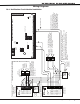
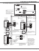
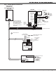
20.7 LX-Bus Module Connection
+
-
Model 716 Output
Expander Module
7m at 12 VDC
Model 717 Graphic
Annunciator
Module
10m at 12 VDC
Normal/Silence Switch
Ground Fault LED
Bell Trouble LED
1 Bell In +
2 Bell In -
3 Bell Out +
4 Bell Out -
5 Bell Trouble
6 Bell Trouble
7 PWR Mon.
8 Mon. RTN
Model 867
Notification Modulè
Bell Power
Supply
12 or 24 VDC
10K EOL Resistor
DMP Model 308
12 or 24 VDC
UL Listed,
Polarized
Notification
Devices
Connect to panel
Supervisory zone
Bell Ring Style
Power Supply Monitor LED
Data LED
To additional LX-Bus Modules
Red
Yellow
Green
Black
LX-Bus™ Wiring
TENS ONES
TENS ONES
Bell Relay
Address
Supervisory
Address
Each LX-Bus Module must
have its own independent
address ranging from 00 to
99. A Supervisory zone must
be programmed into the
XR200 to properly supervise
each module.
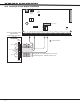
LX-Bus Expansion
Interface Card
DMP Models 462N, 462P,
472, or 481
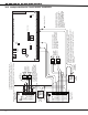
S
S
S
S
S
S
S
S
S
S
S
S
S
= Supervised Circuit
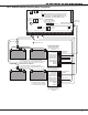
Open Collector
Annunciator Outputs
Relay 1
Relay 2
Relay 3
Relay 4
Optional LED wiring 50mA at
50 VDC resistive
Form C Contacts
Typical
Normally Closed
Common
Normally Open
Optional LED wiring 50mA at
50 VDC resistive