
Installation guide

Digital Monitoring Products XR200 Installation Guide
24
WIRING DIAGRAMS
XR200 Installation Guide Digital Monitoring Products
25
WIRING DIAGRAMS
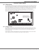
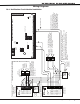
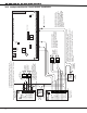
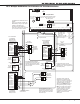
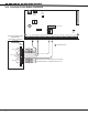
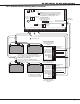
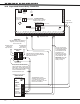
20.6 Supervised Remote Relay Connection
AC
1
2
3
4 5 6 7
8
10
11 12 13 14
15
16 17 18
19
9
20
21
22 23
24
25
26 27
28
+B
BELL
GND
SMK
GND
RED
YEL
GRN
BLK
Z1
Z2 Z3 Z4
Z5
Z6
Z7
Z8 Z9+
Z9-
Z10+
Z10-
AC
-B
GND
GND
GND
GND
XR200 Command Processor™ Panel
J3
DD, MPX
Selection
Headers
J4
Tamper
Header
J2 Output Header
J10
J16
Panel
Reset
J11J12
J6 Interface Card Connector
1 AUX PWR
2 GND
3 Alarm In
4 Bell PWR In
5 Bell Out +
6 Bell Out -
7 Bell Trouble
8 Bell Trouble
866
Module
Normal/Silence Switch
Notification Circuit Module
DMP Model 866
45mA @12 VDC
Remote DPDT
Relay
J2 Output Header
All outputs must be located
within the same room as
the control panel.
K2 K4
K6 K7
Relay Output 1
Use Model 305
Relay Output 2
Use Model 305
Answering Machine
Bypass Relay
Use Model 305
Ground Start Relay
Use Model 305
Model 430
Output Harness
S
= Supervised Circuit
S
S
The 866 Module must be
installed in the panel enclosure
or in a 340FC, 349, or 350
Enclosure connected by no more
than 20 feet of conduit.
DPDT Relay
Use Model ASRB-1 from Advanced
Signaling. 30mA coil operating
current at 12 VDC.
1K EOL
Normally Open
contacts will
close on alarm.
Normally Closed
contacts will
Open on alarm.
10K EOL Resistor
DMP Model 308
DMP Part #DI-001 Rectifier (1N4001
diode) in series with input from Model
866 Module terminal 6.
Wiring between the 866 Module
and the DPDT Relay is supervised
against open, shorts, and grounds.
Any of these trouble conditions will
cause the 866 Module's Bell
Trouble contacts to open.
S
S
The zone connected to
the Bell Trouble contacts
on the 866 Notification
Circuit Module must be
programmed as a
Supervisory Type zone
and selecetd for display
in the Status List. See
Status List section the
XR200 Programming
Guide (LT-0196).