
Installation guide

XR200 Installation Guide Digital Monitoring Products
i
TABLE OF CONTENTS
Revisions to This Document
Product Specications
1.1 Power Supply .........................................1
1.2 Communication.......................................1
1.3 Panel Zones............................................1
1.4 Keypad Data Bus ....................................1
1.5 LX-Bus™ ................................................1
1.6 Outputs..................................................1
1.7 Enclosure Specications ..........................1
Panel Features
2.1 Description.............................................2
2.2 Expansion Zones.....................................2
2.3 Relay Output Expansion ..........................2
2.4 Partitions and Areas ................................3
2.5 Central Station Communication ................3
2.6 Before you Begin ....................................3
2.7 About this Guide .....................................3
2.8 How to Use This Guide............................3
System Components
3.1 Description.............................................4
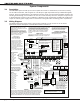
3.2 Wiring Diagram.......................................4
3.3 Lightning Protection ................................5
3.4 Accessory Devices...................................5
Installation
4.1 Mounting the Enclosure...........................6
4.2 Mounting Keypads and
Zone Expansion Modules .........................7
4.3 Connecting Serial Devices........................7
Primary Power Supply
5.1 AC Terminals 1 and 2 ..............................7
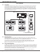
5.2 Transformer Types ..................................7
Secondary Power Supply
6.1 Battery Terminals 3 and 4........................8
6.2 Earth Ground..........................................8
6.3 Battery Only Restart................................8
6.4 Replacement Period ................................8
6.5 Discharge/Recharge ................................8
6.6 Battery Supervision .................................8
6.7 Battery Cutoff.........................................8
6.8 XR200 Power Requirements.....................8
Bell Output
7.1 Terminals 5 and 6 .................................10
Keypad Data Bus
8.1 Description...........................................10
8.2 Terminal 7 - RED ..................................10
8.3 Terminal 8 - YELLOW ............................10
8.4 Terminal 9 - GREEN ..............................10
8.5 Terminal 10 - BLACK .............................10