
Installation guide

Digital Monitoring Products XR200 Installation Guide
22
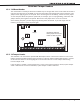
WIRING DIAGRAMS
XR200 Installation Guide Digital Monitoring Products
23
WIRING DIAGRAMS
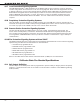
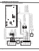
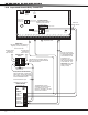
20.5 Remote Station Reversing Relay Connection
AC
1
2
3
4 5 6 7
8
10
11 12 13 14
15
16 17 18
19
9
20
21
22 23
24
25
26 27
28
+B
BELL
GND
SMK
GND
RED
YEL
GRN
BLK
Z1
Z2 Z3 Z4
Z5
Z6
Z7
Z8 Z9+
Z9-
Z10+
Z10-
AC
-B
GND
GND
GND
GND
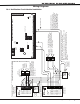
XR200 Command Processor™ Panel
J3
DD, MPX
Selection
Headers
J4
Tamper
Header
J2 Output Header
J10
J16
Panel
Reset
J11J12
462N Network Interface Card
+ -
+
-
Black
Red
+ -
+
-
Black
Red
S
Alternate Alarm
Combo Alarm
Auxiliary Power In
+ Signal Voltage In
+ To Remote Receiver
- To Remote Receiver
- Signal Voltage In
EARTH GROUND
GROUND
GROUND
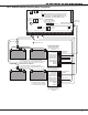
Up to 60 hours of battery standby time can be supplied
using three or four 7.7Ah, sealed, Lead-Acid batteries.
Four 7.7Ah batteries may be required based on total current
draw of all devices connected to the panel. See section
Standby Battery Calculations.
To connect four batteries to the XR200 Command
Processor™ Panel, use three Model 318 Battery Harnesses.
Reversing Relay Module
Radionics Model D127
5mA Standby, 55mA Alarm
@12 VDC
Alternate Alarm
Combo Alarm
Auxiliary Power In
+ Signal Voltage In
+ To Remote Receiver
- To Remote Receiver
- Signal Voltage In
EARTH GROUND
GROUND
GROUND
Reversing Relay Module
Radionics Model D127
5mA Standby, 55mA Alarm
@12 VDC
S
To Telephone Line
To Telephone Line
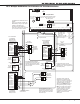
J2 Output Header
All outputs must be located
within the same room as
the control panel.
K2 K4
K6 K7
Relay Output 1
Use Model 305
Relay Output 2
Use Model 305
Answering Machine
Bypass Relay
Use Model 305
Ground Start Relay
Use Model 305
Model 430
Output Harness
S
= Supervised Circuit
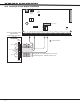
Intended for connection to a
polarity reversal circuit of a
remote station receiving unit
having compatible ratings.
All modules must be installed in a
UL Listed enclosure connected by
no more than 20 feet of conduit.
Fire Alarm Output 3 -
White/Orange
Fire Trouble Output 4 -
White/Yellow
Outputs 3 through 6 supply
up to 50mA at 12 VDC.
Note: Output 3 must be programmed as a Fire Alarm
Output and Output 4 must be programmed as a Fire
Trouble Output. See Output Options section of the
XR200/XR2400F Programming Guide (LT-0196).
S
S
S