
Installation guide

Digital Monitoring Products XR200 Installation Guide
22
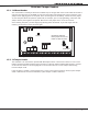
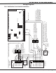
WIRING DIAGRAMS
XR200 Installation Guide Digital Monitoring Products
23
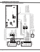
WIRING DIAGRAMS
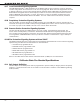
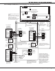
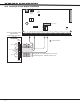
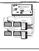
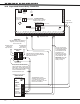
20.4 Dual Style D Zone Module Installation
AC
1
2
3
4 5 6 7
8
10
11 12 13 14
15
16 17 18
19
9
20
21
22 23
24
25
26 27
28
+B
BELL
GND
SMK
GND
RED
YEL
GRN
BLK
Z1
Z2 Z3 Z4
Z5
Z6
Z7
Z8 Z9+
Z9-
Z10+
Z10-
AC
-B
GND
GND
GND
GND
XR200 Command Processor™ Panel
J3
DD, MPX
Selection
Headers
J4
Tamper
Header
J2 Output Header
J10
J16
Panel
Reset
J11J12
J6 Interface Card Connector
GND
Fault A
GND
Fault B
A1
A1
A2
A2
Zone A
GND
Zone B
B2
B2
B1
B1
Zone A
Zone B
Dual Style D Initiating Module
DMP Model 869
25mA Standby, 75mA Alarm
@ 12 VDC
Heat Detectors, manual pull stations, or any other UL
Listed shorting device. Unlimited number of units.
S
S
Aux Power
S
S
S
S
S
S
Model 869
S = Supervised Circuit
SS S S