
Installation guide

Digital Monitoring Products XR200 Installation Guide
20
WIRING DIAGRAMS
XR200 Installation Guide Digital Monitoring Products
21
WIRING DIAGRAMS
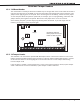
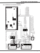
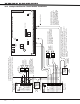
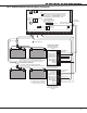
20.2 Multiple Notication Circuit Module Installation
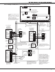
1 AUX PWR
2 GND
3 Alarm In
4 Bell PWR In
5 Bell Out +
6 Bell Out -
7 Bell Trouble
8 Bell Trouble
866
Module
Normal/Silence Switch
10K EOL
DMP Model 308
UL Listed,
Polarized
Notification
Appliances
Style W
UL Listed,
Polarized
Notification
Appliances
Style Z
24 VDC 5
Amp
Maximum
Power Supply Trouble
Contacts N/C
1 AUX PWR
2 GND
3 Alarm In
4 Bell PWR In +
5 Bell PWR In -
6 Bell Out A +
10 Bell Trouble
11 Bell Trouble
865
Module
Normal/Silence Switch
7 Bell Out A -
8 Bell Out B +
9 Bell Out B -
+ -
Notification Circuit Module
DMP Model 866
45mA @12 VDC
To additional 866 Notification Circuit Modules. Up to a
maximum of twenty-five 866 Modules on the XR200 panel.
All modules must be installed in a 340FC, 349, or 350
Enclosure connected by no more than 20 feet of conduit.
S
24 VDC 5
Amp
Maximum
Power Supply
Trouble
Contacts N/C
Auxiliary
Power
Supply
+ -
S
1K EOL
+
-
+
-
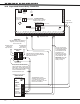
Each 866 Notification Appliance
Circuit Module in alarm draws up to
30mA through its Terminal 3 Alarm
Input and 45mA from its Terminal 1
Aux Power Input.
Each 865 Notification Appliance
Circuit Module in alarm draws up to
59mA through its Terminal 3 Alarm
Input and 26mA from its Terminal 1
Aux Power Input.
The Auxiliary Power Supply and
Notification Circuit Module trouble
contact zone must be programmed
as a Supervisory Type zone and
must be selected for display in the
keypad status list (See Status List
section in the Programming Guide
(LT-0196)).
S = Supervised Circuit
S
S
S
S
S
S
S
S
S
S
S
S
S
S
S
S
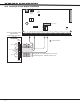
AC
1
2
3
4 5 6 7
8
10
11 12 13 14
15
16 17 18
19
9
20
21
22 23
24
25
26 27
28
+B
BELL
GND
SMK
GND
RED
YEL
GRN
BLK
Z1
Z2 Z3 Z4
Z5
Z6
Z7
Z8 Z9+
Z9-
Z10+
Z10-
AC
-B
GND
GND
GND
GND
XR200 Command Processor™ Panel
J3
DD, MPX
Selection
Headers
J4
Tamper
Header
J2 Output Header
J10
J16
Panel
Reset
J11J12
J6 Interface Card Connector
Auxiliary
Power
Supply
Auxiliary Power Supply must be regulated, UL Listed for Fire Protective
Signaling Service. Power Supplies must have battery backup.
Note: If an auxiliary power supply is not used, terminals 3 and 4 can be
jumpered together to supply Bell Power from the XR200 panel. A
maximum of 1.5 Amps as 12 VDC is available from terminal 5 of the
XR200 panel.
Notification Circuit Module
DMP Model 865
25mA @12 VDC