
Installation guide

Digital Monitoring Products XR200 Installation Guide
18
COMPLIANCE
XR200 Installation Guide Digital Monitoring Products
19
WIRING DIAGRAMS
Wiring Diagrams
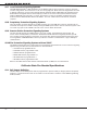
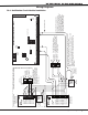
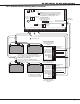
20.1 Notication Circuit Module Installation
1 AUX PWR
2 GND
3 Alarm In
4 Bell PWR In
5 Bell Out +
6 Bell Out -
7 Bell Trouble
8 Bell Trouble
866
Module
Normal/Silence Switch
1 AUX PWR
2 GND
3 Alarm In
4 Bell PWR In +
5 Bell PWR In -
6 Bell Out A +
10 Bell Trouble
11 Bell Trouble
865
Module
Normal/Silence Switch
10K EOL
DMP Model 308
UL Listed,
Polarized
Notification
Appliances
Style W
UL Listed,
Polarized
Notification
Appliances
Style Z
24 VDC 5
Amp
Maximum
Power Supply Trouble
Contacts N/C
7 Bell Out A -
8 Bell Out B +
9 Bell Out B -
Auxiliary
Power
Supply
+ -
Notification Circuit Module
DMP Model 866
45mA @12 VDC
S
24 VDC 5
Amp
Maximum
Power Supply
Trouble
Contacts N/C
Auxiliary
Power
Supply
+ -
S
1K EOL
+
-
+
-
Auxiliary Power Supply must be regulated, UL Listed for Fire Protective
Signaling Service. Power Supplies must have battery backup.
Note: If an auxiliary power supply is not used, terminals 3 and 4 can be
jumpered together to supply Bell Power from the XR200 panel. A
maximum of 1.5 Amps as 12 VDC is available from terminal 5 of the
XR200 panel.
Each 866 Notification Appliance
Circuit Module in alarm draws up to
30mA through its Terminal 3 Alarm
Input and 45mA from its Terminal 1
Aux Power Input.
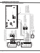
Each 865 Notification Appliance
Circuit Module in alarm draws up to
59mA through its Terminal 3 Alarm
Input and 26mA from its Terminal 1
Aux Power Input.
The Auxiliary Power Supply and
Notification Circuit Module trouble
contact zone must be programmed as
a Supervisory Type zone and must be
selected for display in the keypad
status list (See Status List section in
the Programming Guide (LT-0196)).
S = Supervised Circuit
S
S
S
S
S
S
S
S
S
S
S
S
S
S
S
S
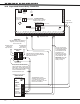
Optional Notification Module Installation
Notification Circuit Module
DMP Model 865
25mA @12 VDC
AC
1
2
3
4 5 6 7
8
10
11 12 13 14
15
16 17 18
19
9
20
21
22 23
24
25
26 27
28
+B
BELL
GND
SMK
GND
RED
YEL
GRN
BLK
Z1
Z2 Z3 Z4
Z5
Z6
Z7
Z8 Z9+
Z9-
Z10+
Z10-
AC
-B
GND
GND
GND
GND
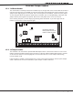
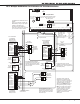
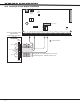
XR200 Command Processor™ Panel
J3
DD, MPX
Selection
Headers
J4
Tamper
Header
J2 Output Header
J10
J16
Panel
Reset
J11J12
J6 Interface Card Connector