
Installation guide
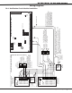

Digital Monitoring Products XR200 Installation Guide
16
COMPLIANCE
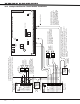
XR200 Installation Guide Digital Monitoring Products
17
COMPLIANCE
UL 985 NFPA 72 (Chapter 2) Specications
Household Fire Warning System Units
17.1 Bell Output Denition
The Bell Output of the Model XR200 must be programmed to operate steady on burglary alarms and pulsed
or temporal on re alarms. See sections 8.4.1 and 8.4.2 of the XR200 Programming Guide (LT-0196).
UL 864 NFPA 72 (Chapter 9) Specications
Control Units for Fire-Protective Signaling Systems
18.1 Zone Restoral Reports
The Restoral Reports option must be selected as Yes or Disarm. See section 6.3 in the XR200 Programming
Guide (LT-0196).
18.2 Power Fail Delay
The Power Fail Delay option must be selected as 6 hours. See section 7.6 of the XR200 Programming Guide
(LT-0196).
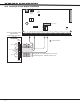
18.3 Sprinkler Supervisory
Any zone used for sprinkler supervisory must be programmed with “SPRINKLR XXX” as the zone name. The
last three characters in the zone name may be assigned a number to identify the zone. The Model 893 Dual
Phone Line Module must be used on all sprinkler supervisory systems.
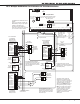
18.4 DACT Systems
Two phone lines must be used. The two phone lines cannot be ground start or party lines. The 893 Dual
Phone Line Module is used to provide connection of two phone lines to the system. The 2ND Phone Line
communication option must be selected as YES. See section 3.3 of the XR200 Programming Guide (LT-0196).
Two different phone numbers must be programmed for digital communication. See sections 3.17 and 3.18 of
the XR200 Programming Guide (LT-0196). The Test Time option must be programmed so that the XR200 sends
a report every 24 hours. See sections 3.8 to 3.10 of the XR200 Programming Guide (LT-0196).
Additionally, you can use the 462N Network Interface Card and the HST (Host) Communication type for
supplementary communication over digital data networks.
18.5 Type 2 and Type 3 Central Station Service
Type 2 and Type 3 Central Station Service can be provided by using MPX communication to the DMP SCS-1
Receiver system. See section 3.2 of the XR200 Programming Guide (LT-0196).
18.6 Type 1 Central Station Service
Type 1 Central Station Service can be provided by using MPX as the main communication and digital dialer
as backup. The 893 Dual Phone Line Module is used to provide connection of the MPX and dialer lines. See
section 3.2 of the XR200 Programming Guide (LT-0196). If Type 1 Central Station service is provided, the Test
Time option must be programmed to send a report every 24 hours. See sections 3.8 to 3.10 of the XR200
Programming Guide (LT-0196).
With both Type 1 and Type 2 Central Station service, the total number of panels assigned to a standard MPX
receiving line of the SCS-1 Receiver System must not exceed 90. This may be increased to 180 by setting the
SNRM option to NO in the SCS-1 Receiver system. This is to allow any signal from a XR200 to be transmitted
to the receiver within 90 seconds.