
Installation guide

Digital Monitoring Products XR200 Installation Guide
14
INSTALLATION
XR200 Installation Guide Digital Monitoring Products
15
INSTALLATION
Reset and Tamper Headers
15.1 J16 Reset Header
The reset header is located just above the terminal strip on the right side of the circuit board and is used to
reset the microprocessor of the XR200. To reset the panel when rst installing the system, install the reset
jumper before applying power to the panel. After connecting the AC and battery, remove the reset jumper.
To reset the panel while the system is operational (for example, prior to reprogramming), install the reset
jumper without powering down the system. Remove the reset jumper after one or two seconds.
After resetting the panel, you must begin programming within 30 minutes. If you wait longer than 30
minutes, you will have to reset the panel again.
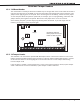
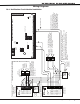
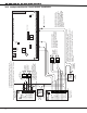
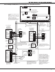
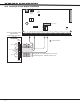
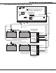
Figure X: XR200 Panel Showing Reset and Tamper Header Positions
15.2 J4 Tamper Header
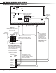
The J4 header is for use with the optional DMP 306 Tamper Harness. The harness connects to one or more
tamper switches mounted inside the panel enclosure to supervise against unauthorized opening or removal
of the enclosure. Refer to the wiring diagram on the enclosure door for correct tamper switch wiring.
How the tamper works
If the enclosure is opened or removed while one or more of the system’s areas are armed, a panel tamper
alarm is indicated. If all areas are disarmed, a panel tamper trouble is indicated.