
Installation guide

Digital Monitoring Products XR200 Installation Guide
12
INSTALLATION
XR200 Installation Guide Digital Monitoring Products
13
INSTALLATION
Dry Contact Relay Outputs
12.1 Description
The XR200 panel provides two auxiliary SPDT relays when equipped with two DMP Model 305 relays in sockets
K6 (Output 1) and K7 (Output 2) and a Model 430 Output Harness. Each relay provides one single pole,
double throw (SPDT) set of contacts that can be operated by any of the functions listed below:
1) Activation by zone condition
Steady
Pulsing
Momentary
Follow
2) Activation by 24-hour 7-day schedule
One on and one off time a day for each relay
3) Manual activation from the Security Command keypad menu
4) Communication failure
5) Armed area annunciation
6) Fire Alarm or Fire Trouble
7) Other system conditions. See the XR200 Programming Guide.
12.2 Contact Rating
The Model 305 relay contacts are rated for 1 Amp at 30 VDC resistive. You can connect auxiliary power to the
common terminal of Relay Output 1 by installing the gray harness wire to terminal 7.
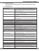
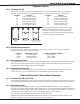
12.3 Output Harness Wiring
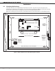
The relay contacts are accessible by installing the DMP 430 Output Harness on the 15-pin header labeled J2.
The contact locations on the wire harness are shown below:
Contact Color
Output 1 normally closed Violet
Output 1 common Gray
Output 1 normally open Orange
Output 2 normally closed Violet
Output 2 common Gray
Output 2 normally open Orange
The relay contacts must be connected to devices located within the same room as the XR200 panel.
12 VDC Voltage Outputs 3 to 10
13.1 Description
The XR200 also provides eight 12 VDC, 50mA resistive voltage outputs on J2 to power external relays or other
devices. The voltage outputs are operated from the same functions as Outputs 1 and 2. See section 12.1.
When connecting any devices to outputs 3 to 10, subtract the current draw of the device from the panel’s
available auxiliary power.
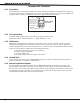
13.2 Output Harness Wiring
The voltage outputs are accessible by installing the DMP 430 Harness on the 15-pin header labeled J2. The
output locations are shown below:
Output Color Output Color Output Color
3 White/Orange 6 White/Blue 9 White
4 White/Yellow 7 White/Violet 10 White/Black
5 White/Green 8 White/Gray Ground Black
Devices connected to the outputs must be located within the same room as the XR200 panel.