
Installation guide

Digital Monitoring Products XR200 Installation Guide
10
INSTALLATION
XR200 Installation Guide Digital Monitoring Products
11
INSTALLATION
Protection Zones
10.1 Terminals 13–24
Zones 1 to 8 (terminals 13 to 24) on the XR200 panel are all grounded burglary zones. For programming
purposes, the zone numbers are 1 through 8. Terminals 13 to 24 provide connection as listed below.
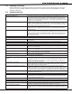
Terminal Function Terminal Function
13 Zone 1 voltage sensing 19 Zone 5 voltage sensing
14 Ground for Zones 1 & 2 20 Ground for Zones 5 & 6
15 Zone 2 voltage sensing 21 Zone 6 voltage sensing
16 Zone 3 voltage sensing 22 Zone 7 voltage sensing
17 Ground for Zones 3 & 4 23 Ground for Zones 7 & 8
18 Zone 4 voltage sensing 24 Zone 8 voltage sensing
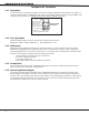
The voltage sensing terminal measures the voltage
through a 1k Ohm End-of-Line resistor to ground.
Dry contact sensing devices can be used in series
(normally-closed) or in parallel (normally-open) with
any of the burglary protection zones.
10.2 Operational parameters
Each protection zone detects three conditions: open, normal, and short. The voltage and resistance
parameters for each condition are listed below:
Condition Resistance on zone Voltage on positive terminal
Open over 1300 ohms over 2.0 VDC
Normal 600 to 1300 ohms 1.2 to 2.0 VDC
Short under 600 ohms under 1.2 VDC
10.3 Zone response time
A condition must be present on a zone for 500 milliseconds before it is detected by the XR200 panel. Ensure
detection devices used on the protection zones are rated for use with this delay. The zones can also be
programmed for a fast response delay of 167 milliseconds.
10.4 Keyswitch arming zone
Using a keyswitch on an Arming type zone allows you to arm and disarm selected areas without having to
enter a user code. For more information refer to the XR200 Programming Guide, LT-0196.
Powered Zones for 2-Wire Smoke Detectors
11.1 Terminals 25–26 and 27–28
Two resettable Class B (Style A) 2-wire powered zones are provided on terminals 25 through 28 on the panel.
For programming purposes the zone numbers are 9 and 10. The UL compatibility identier for the zones is A.
11.2 Zone Information
When using 725 Zone Expansion modules, use UL Listed 6.8k Ohm EOL resistors. The UL compatibility
identier for the zones using 725 Zone expansion modules is B. When using 715 Zone Expansion modules, use
UL Listed 3.3k Ohm EOL resistors (Model 309). When using all other zone expansion modules, use UL Listed
1.0k Ohm EOL resistors (Model 310). The UL compatibility identier for the zones is A.
Do not mix detectors from different manufacturers on the same zone.
Caution: Performing a Sensor Reset will momentarily drop power to the devices on Zones 9 and 10. The
panel will view these zones 10 as “Open” while the power is dropped.
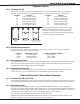
1K Ohm
Normally
Closed
1K Ohm
Normally Open
1K Ohm
Combination Normally Open
and Normally Closed
Figure 4: Protection Zone Wiring