
Installation guide

Digital Monitoring Products XR200 Installation Guide
10
INSTALLATION
XR200 Installation Guide Digital Monitoring Products
11
INSTALLATION
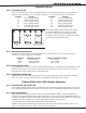
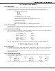
Bell Output
7.1 Terminals 5 and 6
Terminal 5 supplies positive 12 VDC to power alarm bells or horns. The output is rated for a maximum output
of 1.5 Amps. This output can be steady or pulsed depending upon the Bell Action specied in Output Options.
Terminal 6 is the ground reference for the bell circuit.
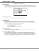
Keypad Data Bus
8.1 Description
Terminals 7, 8, 9, and 10 of the XR200 panel are for the keypad data bus. You can connect up to eight
supervised keypads and an unlimited number of unsupervised keypads to the XR200. In addition to Security
Command keypads, you can also connect any combination of zone expansion modules, 5845LX Glassbreak
detectors and 6155LX PIRs to the data bus. Refer to the device’s Installation sheet for the maximum number
of devices on one keypad or LX-Bus™.
Note: Do not use shielded wire for LX-Bus/Keypad Bus circuits.
8.2 Terminal 7 - RED
This terminal supplies positive 12 VDC to power Security Command® keypads and zone expansion modules.
Terminal 7 also supplies power for any auxiliary device. The ground reference for terminal 7 is terminal 10
with the maximum output rated at 1 Amp.
The output current is shared with the smoke detector output on terminal 11 and Zones 9 and 10. All devices
totalled together must not exceed the panel’s maximum current rating of 1 Amp.
8.3 Terminal 8 - YELLOW
Terminal 8 receives data from keypads and zone expansion modules. It cannot be used for any other
purpose.
8.4 Terminal 9 - GREEN
Terminal 9 transmits data to keypads and zone expansion modules. It cannot be used for any other purpose.
8.5 Terminal 10 - BLACK
Terminal 10 is the ground reference for Security Command keypads, zone expansion modules, and any
auxiliary devices being powered by terminal 7.
Smoke and Glassbreak Detector Output
9.1 Terminals 11 and 12
Terminal 11 supplies positive 12 VDC to power 4-wire smoke detectors and other powered devices. This
output can be turned off by the user for 5 seconds using the Sensor Reset User Menu option to allow latched
devices to reset. Terminal 12 is the ground reference for terminal 11.
9.2 Current Rating
The Output current from terminal 11 is shared with terminals 7, 26, and 28. The total current draw of all
devices powered from the panel must be included with terminal 11 calculations and must not exceed the
maximum output rating of 1 Amp.