
Installation guide

Digital Monitoring Products XR200 Installation Guide
8
INSTALLATION
XR200 Installation Guide Digital Monitoring Products
9
INSTALLATION
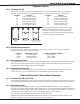
Secondary Power Supply
6.1 Battery Terminals 3 and 4
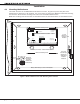
Connect the black battery lead to the negative terminal of the battery. The negative terminal connects
to the enclosure ground internally through the XR200 circuit board. Connect the red battery lead to the
positive terminal of the battery. Observe polarity when connecting the battery.
You can add a second battery in parallel using the DMP Model 318 Dual Battery Harness.
Use sealed lead-acid batteries only: Use the DMP Model 367, 12 VDC 7.0 Ah sealed lead-acid
rechargeable battery. Batteries supplied by DMP or manufactured by Eagle Picher or Yuasa have been
tested to ensure proper charging with DMP products.
GEL CELL BATTERIES CANNOT BE USED WITH THE XR200 PANEL.
6.2 Earth Ground
To provide proper transient suppression, terminal 4 of the XR200 panel must be connected to earth ground
using 14 gauge or larger wire . DMP recommends connecting to a cold water pipe or ground rod only. Do not
connect to an electrical ground or conduit, sprinkler or gas pipes, or to a telephone company ground.
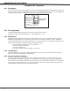
6.3 Battery Only Restart
When powering up the XR200 panel without AC power, short across the CR7 leads to pull in the battery cutoff
relay. The leads need a momentary short only. Once the relay has pulled in, the battery voltage holds it in
that condition. If the XR200 panel is powered up with an AC transformer, the battery cutoff relay is pulled in
automatically.
6.4 Replacement Period
DMP recommends the battery be replaced every 3 to 5 years under normal use.
6.5 Discharge/Recharge
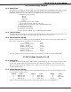
The XR200 battery charging circuit oat charges at 13.9 VDC at a maximum current of 1.2 Amps using a 40 VA
transformer. The total current available is reduced by the combined auxiliary current draw from terminals 5,
6, and 24. The various battery voltage level conditions are listed below:
Battery Trouble: Below 11.9 VDC
Battery Cutoff: Below 10.2 VDC
Battery Restored: Below 12.6 VDC
6.6 Battery Supervision
The XR200 tests the battery when AC power is present. The test is done every 3 minutes and lasts for 5
seconds. During the test, the panel places a load on the battery; if the battery’s voltage falls below 11.9
VDC a low battery is detected. If AC power is not present, a low battery is detected any time the battery
voltage falls below 11.9 VDC.
If a low battery is detected with AC power present, the test is repeated every 2 minutes until the battery
charges above 12.6 VDC; the battery has restored voltage. If a weak battery is replaced with a fully charged
battery, the restored battery will not be detected until the next 2 minute test is done.
6.7 Battery Cutoff
The panel disconnects the battery any time the voltage of the battery drops below 10.2 VDC. This prevents
deep discharge damage to the battery.
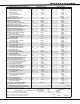
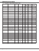
6.8 XR200 Power Requirements
During AC power failure, the XR200 panel and all auxiliary devices connected to the XR200 draw their
power from the battery. All devices must be taken into consideration when calculating the battery standby
capacity. On the following page is a list of the power requirements of the XR200 panel. Add the additional
current draw of Security Command® keypads, zone expansion modules, smoke detector output, and any
other auxiliary devices used in the system for the total current required. The total is then multiplied by the
number of standby hours required to arrive at the total ampere-hours required.