
Installation guide

Digital Monitoring Products XR200 Installation Guide
6
INSTALLATION
XR200 Installation Guide Digital Monitoring Products
7
INSTALLATION
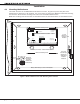
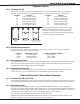
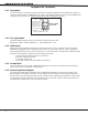
4.2 Mounting Keypads and Zone Expansion Modules
Security Command® keypads have removable covers that allow you to easily mount the keypad to a wall or
other at surface using the screw holes on each corner of the base. Before mounting the base, connect the
keypad wire harness leads to the keypad cable from the panel and to any device wiring run to that location.
Then attach the harness to the pin connector on the PC board, mount the base, and install the keypad cover
making sure all of the keys extend through their respective holes.
For mounting keypads on solid walls, or for applications where conduit is required, use a DMP 775 or 776
keypad conduit backbox for 770 series keypads. To provide additional protection for the keypad against
unauthorized access, install the 777 Plastic Keypad Cover that provides a clear 1/8” thick polycarbonate
housing with locking mechanism. For the 790 series keypads, you can use the Model 695 1-1/2” deep or the
Model 696 1/2” deep backboxes.
DMP zone expansion modules are contained in molded plastic housings with removable covers. The housing
cover contains the module while the base provides you with two mounting holes for installing the unit to a
wall, switch plate, or other surface.
4.3 Connecting Serial Devices
Several factors determine the performance characteristics of the DMP LX-Bus™ and keypad bus: the length
of wire used, the number of devices connected, and the voltage at each device. When planning an LX-Bus™
and keypad bus installation, keep in mind the following four specications:
1. You can install individual keypads on wire runs of up to 500 feet using 22-gauge wire or up to 1,000 feet
using 18-gauge wire. To increase the wire length or add additional devices, a power supply is required.
2. Maximum distance for any one circuit (length of wire) is 2,500 feet regardless of the gauge of wire.
This distance can be in the form of one long wire run or multiple branches with all wiring totaling no
more than 2,500 feet.
3. Maximum number of devices per 2,500 feet circuit is 40. (Note: Each panel allows a specic number
of supervised keypads. Additional keypads can be added in the unsupervised mode. Refer to the
panel’s installation guide for the specic number of supervised keypads that are allowed.)
4. Maximum voltage drop between the panel (or auxiliary power supply) and any device is 2.0 VDC. If the
voltage at any device is less than the required level, an auxiliary power supply should be added at the
end of the circuit.
Refer to the 710 Installation Sheet (LT-0310) for more information. Also see the LX-Bus/Keypad Bus Wiring
Application Note (LT-2031) for additional information.
Expansion Interface Cards (Models 462N, 462P, 462FM, 472, 481, and 482)
The LX-Bus provided on these cards requires only a 4-wire cable between the card and any devices
connected to the bus. You can connect devices (zone or output expansion modules) together on the same
cable or provide separate runs back to the cards. Up to 100 zones or relays are available on each LX-Bus.
Note: Do not use shielded wire when running an LX-Bus or keypad bus. Do not connect the 4 wires from the
Interface Card harness to the panel terminals.
Primary Power Supply
5.1 AC Terminals 1 and 2
Connect the transformer wires to terminals 1 and 2 on the panel. Use no more than 70 ft. of 16 gauge or 40
ft. of 18 gauge wire between the transformer and the XR200.
Always ground the panel before applying power to any devices: The XR200 must be properly
grounded before connecting any devices or applying power to the panel. Proper grounding protects
against Electrostatic Discharge (ESD) that can damage system components. See Earth ground section 6.2.
5.2 Transformer Types
The standard transformer for the XR200 is the Model 321 (16.5 VAC 40 VA). Refer to the XR200 Wiring
Diagram (LT-0204) on the panel enclosure door for a list of optional transformers that can be used with the
panel. The Model 320 wire-in transformer is available when required by the AHJ.
The transformer must be connected to an unswitched 120 VAC 60 Hz electrical outlet with at least 350mA of
available current. Never share the transformer output with any other equipment.