INSTALLATION GUIDE XR200—242-ZONE COMMAND PROCESSOR™ PANEL
MODEL XR200 COMMAND PROCESSOR INSTALLATION GUIDE FCC NOTICE This equipment generates and uses radio frequency energy and, if not installed and used properly in strict accordance with the manufacturer’s instructions, may cause interference with radio and television reception.
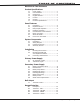
TABLE OF CONTENTS Revisions to This Document Product Specifications 1.1 1.2 1.3 1.4 1.5 1.6 1.7 Power Supply .........................................1 Communication.......................................1 Panel Zones............................................1 Keypad Data Bus ....................................1 LX-Bus™ ................................................1 Outputs..................................................1 Enclosure Specifications ..........................1 Panel Features 2.1 2.
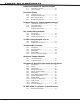
TABLE OF CONTENTS Smoke and Glassbreak Detector Output 9.1 9.2 Terminals 11 and 12..............................10 Current Rating ......................................10 Protection Zones 10.1 10.2 10.3 10.4 Terminals 13–24 ...................................11 Operational parameters .........................11 Zone response time ..............................11 Keyswitch arming zone..........................11 Powered Zones for 2-Wire Smoke Detectors 11.1 11.2 11.2 Terminals 25–26 and 27–28...........
TABLE OF CONTENTS UL 864 NFPA 72 (Chapter 9) Specifications 18.1 18.2 18.3 18.4 18.5 18.6 18.7 18.8 18.9 18.10 Zone Restoral Reports ...........................17 Power Fail Delay ...................................17 Sprinkler Supervisory ............................17 DACT Systems ......................................17 Type 2 and Type 3 Central Station Service ..........................17 Type 1 Central Station Service ...............17 Local Protective Signaling Systems .........
REVISIONS Revisions to This Document This section explains the changes that were made to this document during this revision. This section lists the date the change was made, the section number and section heading, and a quick summary of the change. Date Section Number and Heading Quick Explanation of Changes 12/06 3.2 Wiring Diagram 13.
INTRODUCTION Product Specifications 1.1 Power Supply Transformer Input: 16.5 VAC 40 VA (Models 320 or 321) Standby Battery: 12 VDC 7.7Ah (40 VA charges 2 batteries; 56 VA and 100 VA charges up to 4 batteries) Auxiliary: 12 VDC output at 1 Amp Bell Output: 12 VDC at 1.5 Amp All circuits are inherent Power Limited except the red battery wire. 1.
INTRODUCTION Panel Features 2.1 Description The DMP XR200 Command Processor™ Panel is a versatile 12 VDC, combined burglary and fire communicator panel with battery backup. The XR200 provides 8 on-board burglary zones and 2 on-board 12 VDC Class B powered zones. The powered zones have a reset capability to provide for 2-wire smoke detectors, relays, or other latching devices.
INTRODUCTION 2.4 Partitions and Areas The 20 reporting areas of the XR200 are divided into four separate partitions. Partition 1 provides up to eight individual reporting areas while partitions 2, 3, and 4 each provide up to four individual reporting areas. Keypads installed on the XR200 system are assigned to partitions allowing users to operate the functions of those areas. 2.
INTRODUCTION System Components 3.1 Description The DMP XR200 system is made up of an alarm panel with a built-in communicator, an enclosure, battery, one 16.5 VAC transformer, and a keypad. You can add up to eight supervised Security Command® keypads; wireless, network communications, and expansion interface cards; zone and output expander modules; and initiating and indicating circuit modules.
INTRODUCTION 3.3 Lightning Protection Metal Oxide Varistors and Transient Voltage Suppressors help protect against voltage surges on input and output circuits of the XR200. Additional surge protection is available by installing the DMP 370 or 370RJ Lightning Suppressors. 3.
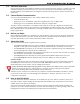
INSTALLATION Installation 4.1 Mounting the Enclosure The metal enclosure for the XR200 must be mounted in a secure, dry place to protect the panel from damage due to tampering or the elements. It is not necessary to remove the XR200 PC board when installing the enclosure. Below are the mounting hole locations for the Model 350A Enclosure. Note: The mounting holes are the same for the 350 Enclosure as those shown below for the 350A Enclosure.
INSTALLATION 4.2 Mounting Keypads and Zone Expansion Modules Security Command® keypads have removable covers that allow you to easily mount the keypad to a wall or other flat surface using the screw holes on each corner of the base. Before mounting the base, connect the keypad wire harness leads to the keypad cable from the panel and to any device wiring run to that location.
INSTALLATION Secondary Power Supply 6.1 Battery Terminals 3 and 4 Connect the black battery lead to the negative terminal of the battery. The negative terminal connects to the enclosure ground internally through the XR200 circuit board. Connect the red battery lead to the positive terminal of the battery. Observe polarity when connecting the battery. You can add a second battery in parallel using the DMP Model 318 Dual Battery Harness. Use sealed lead-acid batteries only: Use the DMP Model 367, 12 VDC 7.
INSTALLATION Standby Battery Power Calculations XR200 Control Panel Relay Outputs 1-2 (ON) Voltage Outputs 3-10 (ON) Active Zones 1-8 Active Zones 9-10 2-Wire Smoke Detectors Panel Bell Output 893/893A Dual Phone Line Module 460 Interface Adaptor Card 462N Network Interface Card 462P Printer Interface Card 472 Inovonics 900MHz Interface Card 481 Expansion Interface Card 485 Enhanced Access Control Expansion Card 865 Style y or Z Notification Module 866 Style W Notification Module 867 LX-Bus Style W Notifica
INSTALLATION Bell Output 7.1 Terminals 5 and 6 Terminal 5 supplies positive 12 VDC to power alarm bells or horns. The output is rated for a maximum output of 1.5 Amps. This output can be steady or pulsed depending upon the Bell Action specified in Output Options. Terminal 6 is the ground reference for the bell circuit. Keypad Data Bus 8.1 Description Terminals 7, 8, 9, and 10 of the XR200 panel are for the keypad data bus.
INSTALLATION Protection Zones 10.1 Terminals 13–24 Zones 1 to 8 (terminals 13 to 24) on the XR200 panel are all grounded burglary zones. For programming purposes, the zone numbers are 1 through 8. Terminals 13 to 24 provide connection as listed below.
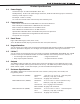
INSTALLATION 11.2 Compatible 2-Wire Smoke Detector Chart Manufacturer Model Detector ID Base Detection Systems DS230, DS230F B/A MB2W, MB2WL A 8.5-33 10 725 Detection Systems DS250, DS250TH B MB2W, MB2WL A 8.5-33 10/12 715, 715-8, 715-16, 725 Detection Systems DS250HD B MB2W, MB2WL A 8.5-33 10 715, 715-8, 715-16 Detection Systems DS260 B/A MB2W, MB2WL A 8.5-33 17 725 Detection Systems DS282, DS282TH B 8.
INSTALLATION Dry Contact Relay Outputs 12.1 Description The XR200 panel provides two auxiliary SPDT relays when equipped with two DMP Model 305 relays in sockets K6 (Output 1) and K7 (Output 2) and a Model 430 Output Harness.
INSTALLATION Telephone RJ Connector 14.1 Description Connect the panel to the public telephone network by installing a DMP 356 RJ Cable between the panel’s J3 connector and the RJ31X or RJ38X phone jack. Set the 3-pin headers labeled J11 and J12 on the XR200 to DD for digital dialer, Contact ID, or Modem IIe operation or MPX for multiplex operation. To Telephone Line Ring Place a jumper across terminals 2 and 7 to provide phone jack supervision, if you are note using the Dual Phone Line Module.
INSTALLATION Reset and Tamper Headers 15.1 J16 Reset Header The reset header is located just above the terminal strip on the right side of the circuit board and is used to reset the microprocessor of the XR200. To reset the panel when first installing the system, install the reset jumper before applying power to the panel. After connecting the AC and battery, remove the reset jumper.
COMPLIANCE Universal UL And NFPA Fire Alarm Specifications 16.1 Introduction The programming and installation specifications contained in this section must be completed when installing the Model XR200 in accordance with any of the UL or NFPA fire standards. Additional specifications may be required by a particular standard. 16.2 Wiring All wiring must be in accordance with NEC, ANSI/NFPA 70. 16.3 Transformer A wire-in transformer should be used. Use the 16.5 VAC 40 VA DMP Model 320.
COMPLIANCE UL 985 NFPA 72 (Chapter 2) Specifications Household Fire Warning System Units 17.1 Bell Output Definition The Bell Output of the Model XR200 must be programmed to operate steady on burglary alarms and pulsed or temporal on fire alarms. See sections 8.4.1 and 8.4.2 of the XR200 Programming Guide (LT-0196). UL 864 NFPA 72 (Chapter 9) Specifications Control Units for Fire-Protective Signaling Systems 18.1 Zone Restoral Reports The Restoral Reports option must be selected as Yes or Disarm.
COMPLIANCE 18.7 Local Protective Signaling Systems The DMP Model 865, 866, or 867 Notification Circuit Module must be used on the bell circuit for detection of shorts and grounds. See sections 25.1 to 25.3 for wiring diagrams. Model 770 series keypads that are used to display troubles for local fire alarm systems must be installed within a DMP Model 777 Keypad Protector.
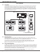
XR200 Installation Guide AUX PWR GND Alarm In Bell PWR In Bell Out + Bell Out Bell Trouble Bell Trouble Notification Circuit Module DMP Model 865 25mA @12 VDC 1 AUX PWR 2 GND 3 Alarm In 4 Bell PWR In + 5 Bell PWR In 6 Bell Out A + 7 Bell Out A 8 Bell Out B + 9 Bell Out B 10 Bell Trouble 11 Bell Trouble 865 Module Normal/Silence Switch Power Supply Trouble Contacts N/C + 24 VDC 5 Auxiliary Amp Power Maximum Supply 1 2 3 4 5 6 7 8 866 Module Normal/Silence Switch Notification Circuit Module DMP Mod
Digital Monitoring Products 20 Notification Circuit Module DMP Model 865 25mA @12 VDC 1 AUX PWR 2 GND 3 Alarm In 4 Bell PWR In + 5 Bell PWR In 6 Bell Out A + 7 Bell Out A 8 Bell Out B + 9 Bell Out B 10 Bell Trouble 11 Bell Trouble 865 Module Normal/Silence Switch Power Supply Trouble Contacts N/C + Auxiliary Power Supply AUX PWR GND Alarm In Bell PWR In Bell Out + Bell Out Bell Trouble Bell Trouble 24 VDC 5 Amp Maximum 1 2 3 4 5 6 7 8 866 Module Normal/Silence Switch S S S S 1K EOL S S S
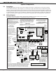
WIRING DIAGRAMS 20.3 Multiple Notification Circuit Modules for Zoned Annunciation J11 XR200 Command Processor™ Panel J4 Tamper Header DD, MPX Selection Headers Answering Machine Bypass Relay Use Model 305 J6 Interface Card Connector J12 J3 J2 Output Header All outputs must be located Ground Start Relay within the same room as K2 K4 Use Model 305 the control panel. To additional Zone 1 Notification Circuit Modules.
WIRING DIAGRAMS 20.
WIRING DIAGRAMS 20.5 Remote Station Reversing Relay Connection J11 XR200 Command Processor™ Panel J4 Tamper Header DD, MPX Selection Headers Answering Machine Bypass Relay Use Model 305 K2 K4 462N Network Interface Card J12 J3 Note: Output 3 must be programmed as a Fire Alarm Output and Output 4 must be programmed as a Fire Trouble Output. See Output Options section of the XR200/XR2400F Programming Guide (LT-0196).
WIRING DIAGRAMS 20.6 Supervised Remote Relay Connection J11 XR200 Command Processor™ Panel J4 Tamper Header DD, MPX Selection Headers Answering Machine Bypass Relay Use Model 305 K2 K4 J6 Interface Card Connector J12 J3 J2 Output Header All outputs must be located within the same room as the control panel.
WIRING DIAGRAMS 20.7 LX-Bus Module Connection LX-Bus Expansion Interface Card DMP Models 462N, 462P, 472, or 481 Model 867 Notification Modulè Normal/Silence Switch Ground Fault LED Bell Trouble LED 12 or 24 VDC Bell Power Supply 10K EOL Resistor DMP Model 308 + - 1 Bell In + 12 or 24 VDC 2 Bell In 3 Bell Out + UL Listed, Polarized Notification Devices 4 Bell Out 5 Bell Trouble 6 Bell Trouble Each LX-Bus Module must have its own independent address ranging from 00 to 99.
Operating Instructions for Model XR200 Panels NORMAL STANDBY CONDITION When the system is in the normal standby condition, the keypad shows either the time of day or a blank display. ALARM CONDITION When the system is in an alarm condition, the keypad display shows the violated zone name(s) followed by an alarm display. ALARM SILENCE To silence the alarm while the bell or siren is sounding, enter your code number and press the COMMAND key.