
Specifications


1070 072 131-102 (96.08) GB
BUEP64 Protocol 9-27
9.11.1.9 Coordination Markers — PW13
The function of the coordination markers is to coordinate the execution of
a command on the PST. The command is only executed when the corre-
sponding coordination event is "true"; the coordination sequence point or
the field coordination marker "1" must therefore be accessed for the
CL500 control type; as far as the other specified control types are con-
cerned, the addressed coordination marker must be "1" for execution of a
coordinated command.
CL500 controller acting as PST
The Central Processing Unit Control command in the CL500 system uses
two types of coordination markers:
- Process coordination marker (PCM) (as of Version 1.2)
and
- as of ZS501: Field coordination marker (FCM)
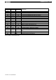
The PCMs are specified as follows:
00 H System STOP status
01 H System RUN status
02 H I / O status
03 H I / O status or STOP
04 H EP
05 H EP or STOP
06 H OM1
07 H OM1 or STOP
0F H Process coordination not permitted in conjunction with
reset PCM disable flag
The FCMs are specified in the special marker area as follows:
- SM16.0 .. SM17.7 single FCM;
these FCMs are reset by the system following execution
of the coordinated command;
- SM18.0 .. SM19.7 permanent FCMs;
are not reset by the system following execution
of the coordinated command;
The FCMs are coded as follows:
SM16.0 .. SM 17.7 ---------> FCM 0 H .. F H
SM18.0 .. SM 19.7 ---------> FCM 10 H .. 1F H
No field coordination -------->FCM FF H