
Specifications


7 – Configuring Controllers
104 R400
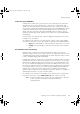
The following timing diagram shows how this works with a radio system.
RS-232 Modem and Radio Link Support
Some devices, such as modems and radio links, are limited not only by the rate at
which they process data, but by whether their links (radio or telephone) are
currently good. These devices sometimes use extra RS-232 lines to signal whether
the device has a good connection.
Modems typically use DCD (RLSD) to signal that they have a good connection.
Other devices sometimes use DSR. The server can be configured to watch either
or both of these lines. If the lines go down, the channel will fail.
To configure your channel to use these settings, on the Quick Builder Port tab for
serial ports, ensure the appropriate Detect DCD or Detect DSR is selected.
Cabling for Stallion EasyConnection
RS-232 Requirements
Most devices have their own particular RS-232 cabling requirements. Refer to the
documentation for your device to determine how to wire your RS-232 cable.
The lines from the Stallion EasyConnection board use the standard RS-232 pin
assignments. The following table lists the standard RS-232 pin assignments.
Figure 7.2 Timing Diagram for RTS/CTS Flow Control
RTS
CTS
DATA
DTE Originated
(Server)
DTE Originated
DCE Originated
(Radio Modem)
RTS is dropped in
order to allow the
radio system to
key transmission
in the other
direction so that
the Controller may
respond to the
Server.
Pin Number Data Line Description
1 Shield Signal Shield
2 TXD Transmit serial data
Table 7.1 Stallion RS-232 Pin Assignments
plscpcg.book Page 104 Monday, May 28, 2001 10:11 AM