
INSTALLATION

PN# 500-19700
Page 4 Rev. C, 8/07
5.2. Installation
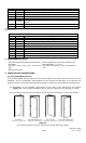
5.2.1. Door Preparation
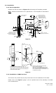
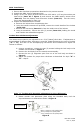
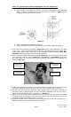
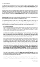
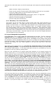
Prepare the door as shown in Figures 3 and 4 using the Template provided.
Note:
Reference dimensions are in parenthesis – see Template for clarification.
1 3/8
35mm
2 1/2
64mm
13/16
21mm
1 1/8
29mm
1/2 Door Thickness
(See Template)
9/16
14mm
O
1
25mm
5/32
4mm
O
1
25mm
O
2 1/8
54mm
O
11/32
9mm
(2 Places)
1 7/32
31mm
O
5/32
4mm
X 5/32 Deep
(2 Places - Each Side of Door)
8.70
221mm
(REF.)
[ 221mm ]
O
3/8
10mm
2 3/4
70mm
Drill O 7/64" [2.8mm]
Pilot hole X 3/4" [19mm]
Deep for #6 X 3/4" Long
(Wood) Mounting Screw
(Battery Side of Door Only!)
2 3/4
70mm
4 1/8
105mm
2 7/16
62mm
1 5/8
41mm
2 1/4
57mm
1 1/8
29mm
Drill O 7/64" [ 2.8mm ]
Pilot Hole X 3/4" [ 19mm ]
Deep for #8-8-32 X 3/4" Long
(Combo) Mounting Screw
(2 Places)
Figure 3
A
A
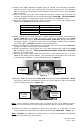
SECTION A-A
40°~
NOTE: Orientation should be as shown - i.e.
the Lower end of hole toward BATTERY CHASSIS
Side of Door and the Upper end of hole toward the
FACE PLATE Side of Door.
Drill Thru
O
5/16" From
O
2 1/8" Hole
to
O
1" Hole at ~40
v
Angle
(Note The 11/32" Offset from the
O
11/32"
Hole - This ensures that the Motor Wires
will not interfere with the 10-32 UNF X 2-1/2"
Long Mounting Screw)
O
(1)
O
(11/32)
11/32
(REF.)
(Offset)
5/16
[8mm]
Figure 4
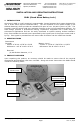
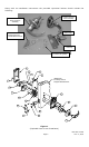
5.2.2. Installation of SABL into Door
This section will provide step-by-step instructions for the installation of the SABL.
Please refer to the Figure 1 (page 2) for an exploded view of the assembly of a SABL
into a wooden door.