
Install

PN# 500-22100
Page 9 Rev. F, 04/11
6. OPERATING INSTRUCTIONS
The Gate Lock is a direct latching fail safe/locked electromechanical lock which incorporates
Securitron’s unique dual voltage system. The GL1 does NOT automatically re-lock if the strike
is not moved from the latch. The strike must always be pushed closed to mechanically re-
latch in order for the GL1 to re-lock.
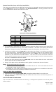
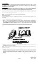
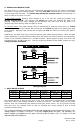
In Fail Locked mode: Applying input voltage of 12 or 24 volts DC, observing polarity (See
Wiring diagram below), will energize and unlock the Gate Lock allowing the gate to be
opened. Removing the input voltage will de-energize the Gate Lock and will allow it to
mechanically latch securely when the gate is closed.
In Fail Safe mode: The input voltage must be maintained to keep the Gate Lock in a locked
mode. Removing the input voltage will de-energize and unlock the Gate Lock allowing the gate
to be opened. Applying input voltage will energize and lock the Gate Lock awaiting the gate to
be closed.
Additionally, the Gate Lock may include an optional gate status sensing feature. When the gate
(strike assembly) is latched closed the Gate Lock will report this closed condition by outputting a
closed circuit condition between the C and NC terminals. When the gate is open, the closure will
be between the C and NO terminals. This dry Single Pole Double Throw (SPDT) output can carry
1 Amp @ 30VDC maximum.
Wiring Diagram
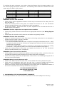
7. WIRE GAUGE SIZING
Distance Gauge 12V Gauge 24V
Distance Gauge 12V Gauge 24V
100 FT 20 GA 22 GA 800 FT 12 GA 14 GA
200 FT 18 GA 20 GA 1500 FT 10 GA 10 GA
400 FT 14 GA 16 GA 2000 FT 8 GA 8 GA
The general practice of wire sizing in a DC circuit is to avoid causing voltage drops in connecting
wires that reduce the voltage available to operate the device. As Gate Locks are low power
devices, they can be operated long distances from their power source. For any job that includes
long wire runs, the installer must be able to calculate the correct gauge of wire to avoid
excessive voltage drops.
This is done by taking the current draw of the lock and multiplying by the resistance of the wire I x R =
Voltage drop (i.e. 0.7 Amp. x 1.6 Ohms = 1.12 Volts dropped across the wire). For example a 5%
drop in voltage is acceptable so if this were a 24 Volt system (24 Volts x .05 = 1.2 Volts) a 1.12 Volt
drop would be within tolerance.