
Instruction Manual

10
500-22090, Rev A
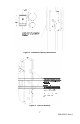
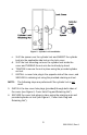
Figure 6. Cover Hole Plug and Retaining Nut
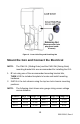
Mount the GL1 and Connect the Electrical
NOTE: The FMK-SL (Sliding Gate) and the FMK-SW (Swing Gate)
mounting bracket kits are recommended for installing the GL1.
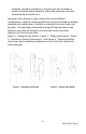
1. IF not using one of the recommended mounting bracket kits,
THEN USE the included template to locate and install mounting
hardware.
2. INSTALL the lock chassis using the top two lock chassis mounting
positions.
NOTE: The following chart shows wire gauge sizing versus voltage
versus distance:
Distance Gauge 12V Gauge 24V Distance Gauge 12V Gauge 24V
100 FT 20 GA 22 GA 800 FT 12 GA 14 GA
200 FT 18 GA 20 GA 1500 FT 10 GA 10 GA
400 FT 14 GA 16 GA 2000 FT 8 GA 8 GA