
Manual

PN# 500-19200
Page 2 Rev. G, 08/11
5.1. WIRE GAUGE SIZING
If the power supply is at a distance from the device, voltage will be lost (dropped) in the
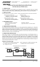
connecting wires so that the unit will not receive full voltage. The following chart shows the
minimum wire gauge that will hold voltage drop to an acceptable 5% for different device to
power supply distances. Proper use of the chart assumes a dedicated pair of wires to power
each unit (no common negative). Note that a device operating on 24 volts is a much better
choice for long wire runs as it has 4 times the resistance of a 12 volt installation. Also note
that the correct calculation of wire sizing is a very important issue as the installer is
responsible to insure that adequate voltage is supplied to any load. In multiple unit
installations, the calculation can become quite complex so refer to Section 7 Appendix A for a
more complete discussion.
Distance Gauge 12V Gauge 24V
Distance Gauge 12V Gauge 24V
80 FT 20 GA 24 GA 800 FT 10 GA 16 GA
200 FT 17 GA 22 GA 1500 FT 8 GA 14 GA
400 FT 14 GA 20 GA 3000 FT N/A 12 GA
CALCULATING WIRE GAUGE SIZING - The general practice of wire sizing in a DC circuit is to
avoid causing voltage drops in connecting wires that reduce the voltage available to operate the
device. As the FSUNL is a very low power device, it can be operated long distances from its
power source. For any job that includes long wire runs, the installer must be able to calculate
the correct gauge of wire to avoid excessive voltage drops.
This is done by taking the current draw of the lock and multiplying by the resistance of the wire I
x R = Voltage drop (i.e. 0.100A x 10.1 Ohms = 1.01 Volts dropped across the wire). For all
intents and purposes it can be said that a 5% drop in voltage is acceptable so if this were a 24
Volt system (24 Volts x .05 = 1.2 Volts) a 1.01 Volt drop would be within tolerance.
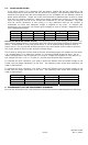
To calculate the wire resistance, you need to know the distance from the power supply to the
FSUNL and the gauge (thickness) of the wire. The following chart shows wire resistance per
1000 ft (305 meters):
To calculate the wire resistance, you need to know the distance from the power supply to the
FSUNL and the gauge (thickness) of the wire. The following chart shows wire resistance per
1000 ft (305 meters):
Wire Gauge Resistance/1,000 ft
Wire Gauge Resistance/1,000 ft
8 Gauge .6 Ohms 16 Gauge 4.1 Ohms
10 Gauge 1.0 Ohms 18 Gauge 6.4 Ohms
12 Gauge 1.6 Ohms 20 Gauge 10.1 Ohms
14 Gauge 2.5 Ohms 22 Gauge 16.0 Ohms
6. MAGNACARE
LIFETIME REPLACEMENT WARRANTY
For warranty information visit: www.securitron.com/en/site/securitron/About/MagnaCare-Warranty/