
Installation Instructions
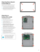
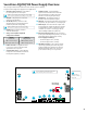

Securitron AQL6 Power Supply Overview
This guide gives the basic information needed to install a system containing
a single Securitron AQL Power supply for most applications.
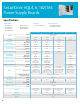
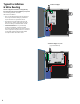
1 AC Input Voltage Selection – Leave INTACT
for 120 V input. CUT for 230 V input.
Failure to cut this jumper when using the Securitron AQL
with a 230VAC input will result in damage to the system.
2 AC Input – The primary AC connection.
Cut JP1 for 230 VAC input.
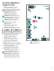
3 AC ON LED (GREEN) – Indicates a valid
AC input voltage is present. Missing AC is
indicated by this LED extinguishing.
Always confirm the absence of AC power with a
meter before servicing to prevent electric shock.
4 FAI LED (RED) – Indicates activation
of the Fire Alarm Input.
5 Charge Current / Main Output FAI
Configuration Switches
SWITCH 1
FAI Selection
SWITCH 2
Charge Current
OFF = Constant Output OFF = High Charge Current
ON = Output switches on FAI ON = Low Charge Current
6 FLEX IO Connector – Supplies FAI status
to any accessory boards. Receives fault
signal from accessory boards.
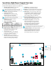
7 System Fault Contact – Contact labeling
is adjacent to the terminals and shown in
the unpowered (FAULT) condition.
8 AC Fault Contact – Contact labeling is
adjacent to the terminals and shown in the
unpowered (FAULT) condition. AC fault is
indicated on a missing AC Input voltage.
9 AUX Voltage – The auxiliary voltage is a
fixed Class 2 Power Limited DC output.
10 FAI Input – The input from the FACP. Can be wired to
accept a NO, NC, Open Collector, or Voltage input.
11 Main Output – This is the main DC output of the
power supply. The output can either be constant
or switched based on the configuration setting
of switch 1 (see number 5 on this page). The DC
ON LED will light: GREEN 12 V | BLUE 24 V.
12 Battery Terminal Connection – The connection
for the optional backup battery. Battery set voltage
must match the DC output voltage setting.
13 12/24 V Selection Jumper – This selects the
output voltage between 12 V and 24 V DC.
The Securitron AQL Power supply must be
completely powered down before changing
this setting. Voltage markings are printed
on the PC Board adjacent to the selector.
Remove AC input power before changing the voltage select switch
to avoid damaging the power supply or connected equipment.
14 DataLink Connection – This connector allows
optional programming and monitoring of the
Securitron AQL power supply via an optional
NetLink network module. See the instructions
for the Netlink module for more information.
FAI INPUTFAI INPUTSYS FLTSYS FLT
AC FLTAC FLT AUXAUX
N
L
+
–
1 2
ON
1 2
AC Select
10
11
12
13
14
1
2
3
6
4
5
7
8
9
Observe battery
polarity or damage
may result
For UL compliance, the AC fault contact must
be monitored by a listed control panel
8