
Installation Instructions
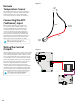

Remote
Temperature Sensor
The remote temperature sensor allows measuring a
temperature up to 6 feet away from the Securitron
NL4 board. Plug the sensor into J18 and run the
sensor wire to the area or device to be monitored.
Connecting the ADC
(Voltmeter) Input
When using the voltmeter input, connect one
end of the ADC cable to the ADC1 input on the
Securitron Netlink board. Cut off the other end
of the ADC cable and connect it to the voltage
source to be monitored, observing polarity. The
red wire is the positive input and the black wire is
the negative (DC Common) input. The ADC cable
wiring must be routed away from high voltages and
the wire used must be rated for the voltages and
temperatures in the area in which it is installed.
NOTE: The voltage being measured by the ADC
input MUST be common grounded with the voltage
source of the Securitron Netlink board.
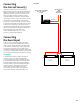
Wiring the Control
Outputs
When using the control outputs, connect one end of the
Control Output cable to the Control Outputs connector
on the Securitron Netlink. Cut off the other end of the
control output cable. The wire going to the pin on the
connector labeled “FLT” is Control Output # 1. The wire
going to the pin labeled “EN_FAI” is Control Output #2.
The Control Outputs are low-current, open collector
(transistor) outputs which pull to ground when
activated. These outputs can be used to activate
sensitive trip relays such as LifeSafety Power’s RB Series,
supply the ground side to an FAI Input, or other similar
uses. See Diagram 7, for an example using an RB relay.
NOTE: Do not connect these outputs directly to a voltage
source or damage to the Securitron Netlink will occur.
Also, ensure the wire used is rated for the voltages
and temperatures in the area which it is installed.
–
+
9-28
VDC
Tamper
Switch
Black
Red
Event
Input
NETLINK
CONTROL
OUTPUT
+
–
P-
T-
P+
DC1
Diagram 6
Diagram 7
22