
Installation Instructions

Module Overview
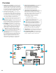
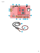
The following are basic Securitron Netlink board descriptions.
Refer to the appropriate section for more detailed information.
1 C1 and C2 Inputs (J12 & J16) – These are the
connectors for the current sensors. Only NL4 current
sensor should be plugged into this connector. The
sensors have a range of +/-20 A and are typically used
to monitor battery discharge current. See page 22.
2 Event 1 Input (J14) – This is the connector for
the Event1 input. This input will accept 9-30 VDC
to initiate an event alert. This input will only
indicate an active or inactive condition and will
not measure the voltage level. See page 21.
3 ADC1 Input (J15) – This is the Analog to Digital
Converter (ADC) input, which acts as a voltmeter.
It accepts 0-30 V and is used to measure
positive or negative system voltages which
are common grounded with the Securitron
Netlink board. The ADC cable wiring must be
routed away from high voltages. See page 22.
4 Input V+ & V- (J1 & J3) – This is the power input
for the Securitron Netlink board. This input accepts
8 to 30 VDC ONLY from any power supply.
NOTE: The voltage input of the Securitron Netlink
must be connected directly to the main or aux
output or to the AUX input of the power supply.
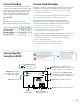
5 Ethernet Connection (SK1) – This is the RJ45
jack for the network connection. The ethernet
cable is plugged into this jack. See page 20.
6 Status LED Indicators (D2, D3, D4) – These
LEDs indicate the status of the Ethernet
link to the Securitron Netlink board.
LED Indicator:
› GREEN (LINK) Lights when Securitron
Netlink is connected to a network
› RED (DATA) Flashes during data transfer
› BLUE (SYS) Lights when the Securitron Netlink is
fully booted up and running. During the bootup
process, this LED may flash on and off several
times. The Securitron Netlink will not be able
to be accessed until this LED lights steady.
7 External Temperature Sensor (J18) – This connector
is for the external temperature sensor. See page 22.
8 Future use (J9) – This jumper is reserved
for future use and should be left OFF.
9 Event1 Input Invert Jumper (J8) – This jumper
inverts the action of the Event 1 Input. See page 21.
Jumper Position:
› OFF Event 1 active when voltage is applied
› ON Event 1 active when voltage is removed
10 Backup Battery (BT1) – This is the coin cell battery for
maintaining the clock when all power is removed from
the Securitron Netlink. The battery type is CR2032.
11 Factory Reset Button (SW1) – This button
resets the User Name, Password, and IP Address
settings back to factory default. Typically used
when IP and/or login information has been
lost. See page 24 for more information.
12 Device 1 – Device xx (J4, J5, J11, J17) – Data is passed
between the Securitron Netlink board and it’s
connected devices through these Device serial port
links. The NL4 has four serial links to monitor up to four
devices (maximum combination of two AQL). AQL must
connect to Device 1 and 2 respectively. See page 20.
13 Control Outputs (J10) – This connector is for the
two control outputs. These outputs are open
collector (transistor) low-current outputs for
use with RB Relay Boards or other low-current
inputs. The Control Output cable wiring must be
routed away from high voltages. See page 22.
14 Enable 100Mbps (J19) – If present, this jumper enables
100Mbps speed for the network connection.
15 Future Use (J20 & J22) – If present, these jumpers
are reserved for future use and should be left OFF.
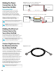
16 Current Sensor – Current Lead 1 (SHORT) – The
short orange lead connects in-line with the current
to be measured toward the more negative side of
the current flow. Positive current is measured when
current flows from Current Lead 2 (Long Lead) to
Current Lead 1 (Short Lead). When using to measure
battery discharge current, this lead goes to the
BAT+ terminal on the power supply. See page 21.
17 Current Sensor – Current Lead 2 (LONG) – The
long red lead connects in-line with the current to
be measured toward the more positive side of the
current flow. Positive current is measured when
current flows from Current Lead 2 (Long Lead)
to Current Lead 1 (Short Lead). When using to
measure battery discharge current, this lead goes
toward the positive battery terminal. See page 21.
18 Current Sensor – Data Connector – This connector
connects to the Securitron Netlink board’s C1
or C2 input (J12 or J16) to provide the current
reading to the Securitron Netlink. See page 21.
18