
Installation Instructions
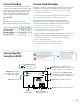

Overview
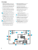
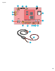
1 DC IN Connectors (J1 & J4) – These fastons are the
input to the Securitron B100. Either faston may be
used as the input. Two connections are provided to
allow this voltage to pass through to other accessory
boards in the system. This input voltage must always
be at least 3 volts above the output voltage setting
for the Securitron B100 to maintain its output.
2 DC OUT Connectors (J2 & J5) – These fastons are
the output of the Securitron B100 for connection
to other accessories in the system. This output may
be considered as an equivalent to the main output
of an Securitron AQL power supply. Either or both
DC OUT fastons may be used in the system.
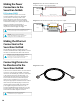
Ensure there are no other voltage sources connected to the
buss before powering the system or damage WILL occur.
3 BR Connectors (J3 & J6) – The DC Common buss in
the system. All boards in the system must have their
BR fastons wired together for proper operation.
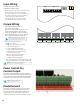
4 DC IN LED (D1) (BLUE/GREEN) – This LED indicates
the availability of voltage on the DC IN Buss. When
voltage is available on the buss, the LED is lit. This
LED is bi-color and indicates the input voltage as
follows: GREEN – 12 V Input | BLUE – 24 V Input
NOTE LED colors are range based. Voltage Less than 13 V
will show Green. Voltage above 20V will show Blue. Voltage
between 13 and 20 may show either voltage or a combination
Green & Blue. Always verify voltage with a voltmeter
5 FAULT LED (D7) (YELLOW) – This LED lights when
the Securitron B100 detects a fault condition. This
fault condition also transmits to the Securitron
AQL power supply. Fault conditions detected
include ruptured output fuse, no output, output
overload, or output voltage out of regulation.
6 FlexIO Connectors (JP1 & JP2) – These connectors
allow the fault status of the Securitron B100
to be transmitted to the Securitron AQL
power supply and pass the FlexIO buss on to
other accessory boards in the system.
7 Output Voltage Selection (JP3 & VR1) – This
jumper selects the output voltage for the Securitron
B100 and the potentiometer sets the output
voltage when in the adjustable range. In adjustable
range, voltage may be set from 5 to 18 VDC.
Possible jumper settings are as follows:
• 12 V Out JP3 Position 1
• Adjustable Output JP3 Position 2
The VR1 potentiometer will have no effect unless
the jumper is set for the adjustable range
NOTE that the input must be at least 3 V above the output
voltage setting or the Securitron B100 will display a
fault condition. It may be helpful to temporarily set the
input power supply to 24 V (Remove load devices first)
before setting the Securitron B100 output voltage.
8 DC Output – This is the output terminal strip. This
terminal strip is nonremovable and accepts wire
sizes from AWG 12 – AWG 22. The terminals are
labeled on the PC board by the terminal strip.
9 Output Fuse (F1) – This fuse protects the DC Output
terminals. It does not protect the DC OUT faston.
10 DC OUT LED (D4) (GREEN) – This LED indicates the
availability of voltage on the DC OUT Buss. When
voltage is available on the buss, the LED is lit.
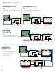
DC IN
DC OUT
BR
DC IN
BR
DC OUT
– OUT +
Fault
DC In
DC Out
1
1
2 2
3
3
8
5
4
10
9
6
7
14