
Installation Instructions
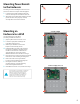

Securitron
®
D8/D8P
Power Distribution
Module
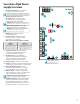
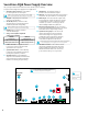
Overview
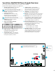
1 FlexIO Connectors – These connectors
pass the FlexIO buss through the D8 to
other accessory boards in the system.
2 B1 Connectors (J1 & J4) – These fastons are for
connection to the B1 voltage buss in the system.
The voltage on the B1 buss comes from the main
output of an Securitron AQL power supply. This
voltage will be directed to any outputs whose
Output Selection Jumper is set in the B1 position.
3 B2 Connectors (J3 & J5) – These fastons are for
connection to the B2 voltage buss in the system.
The voltage on the B2 buss comes from the main
output of an Securitron AQL power supply in a dual
voltage system. This voltage will be directed to any
outputs whose Output Selection Jumper is set in
the B2 position. If the D8 is being used in a single
voltage system, these fastons can be left unused.
4 BR Connectors (J2 & J6) – The DC Common buss in
the system. All boards in the system must have their
BR fastons wired together for proper operation.
5 Output Selection Jumpers (JP1 – JP8) – These
jumpers select which voltage buss input is selected
for the output. Jumper numbers correspond
with the zone number (e.g. JP1 is the jumper
for OUT1). Possible settings are as follows:
• Position 2 (LEFT) – B2 Buss
• Position 1 (RIGHT) – B1 Buss
• Removed – Disable Output
6 Output Fuses (F1 – D8) – When using the fused version
of the D8, these are the fuses for each zone output. Fuse
numbers correspond with the zone number (e.g. F1 is
the fuse for OUT1). When using the PTC version of the
D8, the fuse will be replaced with a soldered-in PTC.
7 Output LEDs (D1 – D8) (Dual Color – GREEN/BLUE)
– These LEDs indicate the availability of voltage on
a zone’s output. When voltage is available on the
output terminals, the LED is lit. GREEN 12 VDC |
BLUE 24 VDC. LED numbers correspond with the
zone number (e.g. D1 is the LED for OUT1).
8 Zone Outputs (Out1 – Out8) – These are the
zone output terminal strips. These terminal
strips are removable and accept wire sizes from
AWG 14 – AWG 22. The terminals are labeled on
the PC board underneath the terminal strip.
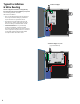
CAUTION When
powering magnetic loads
such as maglocks, door
strikes, solenoids, etc,
each of these loads must
have a reverse protection
diode either built-in or
external to the device
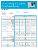
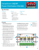
Specifications
Certifications
• UL 294 Listed
• UL 603 Listed
• UL 1076 Listed
• ULC-S318 Listed
• ULC-S319 Listed
• CSA C22.2 #107.1
• RoHS Compliant
• CSFM Approved
• FCC Part 15, Subpart B
Electrical
• 8 continuous outputs
• Input
x Voltage: 5-24 VDC nominal
x Current: 12 A maximum
x Standby Current: 65 mA
• Output
x Voltage: same as input
x D8 Current: 3 A resistive fuse
3 A ATM automotive style
x D8P Current: 2.5 A resistive
(Class 2 Power Ltd)
Shipping Weight
• .15 lbs
Dimensions
• 4" x 2.5" x 1"
[102mm x 64mm x 25mm]
+ –
OUT1
+ –
OUT2
+ –
OUT3
+ –
OUT4
+ –
OUT5
+ –
OUT6
+ –
OUT7
+ –
OUT8
JP1
B1
B2
BR
B1
B2
BR
F1
F2
F3
F4
F5
F6
F7
F8
JP2 JP3 JP4 JP5 JP6 JP7 JP8
2
12 12 12 12 12 12 12 1
FLEXIOFLEXIO
FLEXIOFLEXIOFLEXIOFLEXIO
1 1
7
2
3
4
5
2
6
4
8
3
10