
User's Manual

SW-ATT-TAKRF preliminary manual 04-18-2012 RevB.docx
Page 6 of 7
Important:
1. All of the zones in the TAKRF are “normally closed” zones.
2. The loop resistance should be between 2.2k and 6k Ohms. If the loop resistance is out
of range, then the end of line resistor must be changed or the wiring must be repaired.
WARNING: The TAKRF cannot be used to power or monitor any type of Fire or CO
detection zone.
NOTICE: The TAKRF does not power or monitor PIR or Glass Break devices.
SPECIFICATIONS:
Wireless signal range: ??? 350ft, open air
Code Outputs: For device: Power up, Tamper, Low battery,
Supervisory, AC power, DC (battery) power
For each Zone: Open, Short, Restore
Transmitter frequency: 433.92 MHz +/- ???
Supervisory Interval: 60-70 min
Peak Field Strength: ????
Dimensions: Approx 4.75 x 3.00 x 1.5 in
Weight: Approx 8.0 Oz
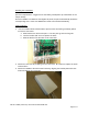
Housing: ABS plastic
Color: White
Operating Temperature: 32F to 120F (0C to 49C)
Relative Humidity: 5-95% non-condensing
Operating Voltage: 9-16 VDC, ???mA
Regulatory Listing(s) UL, FCC part 15 (both pending)
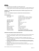
Included Accessories: Mounting plate, two (2) screws, two (2) plastic
drywall anchors, one (1) 14VDC power supply
IMPORTANT INFORMATION ABOUT RADIO DEVICES
1. AT&T radio controls provide a reliable communications link and fill an important need in
portable wireless signaling. However, there are some limitations which must be
observed.
2. For US installations only: the radios are required to comply with FCC rules and
regulations including FCC part 15 devices. As such, they have limited transmitter power
and therefore limited range.
3. A receiver cannot respond to more than one transmitted signal at a time and may be
blocked by radio signals that occur on or near their operating frequencies regardless of
code settings.
4. Changes or modifications to the device may void FCC compliance
5. Infrequently used radio links should be tested regularly to protect against undetected
interference or fault.