
User's Manual
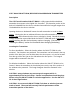

Using a flat head screwdriver
pop off the top cap. Pull the
units out of the case.
Replace with new battery. ( + )
or positive polarity should be
facing up. Slide unit back into
the case
Replace Cover
Note: Make sure you
properly slide the unit into
the channel for proper fit
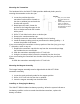
1. Remove the transmitter assembly from the door or window jam.
2. Remove the cap from the transmitter
assembly.
3. Carefully remove the transmitter circuit board
from its housing.
4. Remove the depleted battery and dispose of it
as required by local laws.
5. Insert the replacement battery paying careful
attention to the battery polarity. + is the side nearest the
transmitter printed circuit board.
6. Reinsert the transmitter assembly into its housing.
7. Replace the cap for the transmitter assembly.
8. Insert the transmitter assembly into the door or window jam.
9. Install the screws for securing the transmitter (if they were used in the
initial installation process.)
10. Test the SW-ATT-RDW to assure that it is working properly.
Enrolling the Transmitter
(Per AT&T requirements)
Verifying the programming and RF communications
(Per AT&T requirements)
General Specifications
Operating Temperature: 32° to 120° F (0° to 49° C)
Operating Rel. Humidity: 5 to 95%, non-condensing
Operating Frequency: 433.92 MHz
Battery Type: 3-Volt CR2 Lithium Battery
IMPORTANT INFORMATION ABOUT RADIO DEVICES
1. AT&T radio controls provide a reliable communications link and fill an important
need in portable wireless signaling. However, there are some limitations which
must be observed.
2. For US installations only: the radios are required to comply with FCC rules and
regulations including FCC part 15 devices. As such, they have limited transmitter
power and therefore limited range.
3. A receiver cannot respond to more than one transmitted signal at a time and may
be blocked by radio signals that occur on or near their operating frequencies
regardless of code settings.