
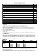
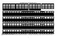
Technical data
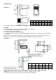
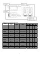

ACCESS TO THE UNIT COMPARTMENT AND EVAPORATOR HOUSING
Wall Model
Front Panel:
Grasp each side of the front panel and “pull forward” releasing it from the spring clips
located down each edge, it may be necessary to separate the front panel from the main
body using a flat blade screwdriver and gently ease away.
Condenser Fan
Assembly
After removing the front panel “pull upwards” the condenser fan housing assembly to
release it from the 4 “spring clips” located in each corner.
It may be necessary to separate the fan housing assembly from the main body using a
flat blade screwdriver and gently easing upwards.
Evaporator fan
assembly
Remove the screw securing the drain tube to the drip tray and remove the drain tube
Remove the four screws securing the drain pan and remove.
Remove the three remaining screws securing the side panel and remove it allowing
access into the evaporator fan assembly.
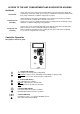
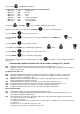
Controller Operation
Description of electronic panel
2. Control LED (Green):
ON
: evaporator fan is running.
Flashing
: evaporator fan is in start mode.
OFF
: evaporator is off. Defrost in operation
1. Control LED (Green):
LIT
: Compressor running, Unit is refrigerating
FLASHING
: Compressor is in start delay mode (waiting for signal to start)
OFF
: Compressor is OFF. Room is down to temperature.
3. Control LED (Yellow):
LIT: Unit in defrost mode (auto or manual)
Flashing: Manual defrost mode in operation.
4. Alarm LED (Red):
LIT: Alarm is active – see separate ALARMS section.
OFF: Unit is functioning normally