
Technical data

20
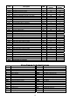
Label Description DIM
Medium Temp
Settings
Low Temp
Settings
CP Compressor Parameters
dIF Differential °C/1 2 2
HSE Maximum allowed set point °C/1 10 -15
LSE Minimum allowed set point °C/1 -5 -25
Ont Compressor ON time if room sensor fails min 10 10
OFt Compressor OFF time if room sensor fails min 20 20
dOF Time between Compressor OFF and next start min 2 2
dbi Time between 2 compressor starts min 2 2
dEF Defrost Parameters
dtY Defrost type: 1= Hot Gas. 0 = Electric num 1 1
Dit Time interval between 2 defrosts hours 3 3
dCt Defrost interval time count mode num 0 0
dEt Defrost time override min 20 20
dSt Defrost termination temperature °C/1 15 15
FAn Fan Parameters
FSt Fan stop temperature °C/1 50 50
Fdt Fan delay time min 3 3
dt Drain down time min 2 2
dFd Fans OFF during defrost flag Y Y
FCO Fans ON when compressor OFF flag Y Y
FOd Fans OFF when door open flag n n
AL Alarm Parameters
AFd Alarm differential °C/1 2 2
HAL High temperature alarm set point °C/1 5 5
LAL Low temperature alarm set point °C/1 -5 -5
PAO Alarm delay after start up hours 3 6
dAo Alarm delay after defrost min 60 60
OAO Alarm delay after door opening hours 1 1
SA3 High temperature alarm set point °C/1 55 55
dA3 Differential °C/1 2 2
PrE Pressure Alarm Parameters
PEn Number of pressure trips num 10 10
PEI Time period for pressure trips min 60 60
diS Display Parameters
CA1 Room sensor calibration °C 0 0
drO Celsius or Fahrenheit temperature: 0 =°C. 1 = °F flag 0 0
CnF Configuration Parameters
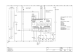
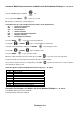
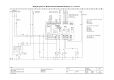
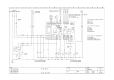
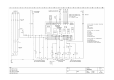
Wiring Diagram Code Identifications
BA
Room Sensor
FTE
Emergency ‘Stat
BC
Condenser Alarm Sensor
HI
Alarm
BS
Defrost Sensor
K1
Contactor
BVR
Speed Regulator
K11
Defrost Contactor
BVRS
Speed Regulator Sensor
M1
Compressor Motor Nr.1
E
Defrost Heater
MPC
Door Microswitch (Room)
E1
Resistenza Carter Compressore
MVC
Condenser Fan Motor
M1
Compressor Crankcase Heater
MVE
Evaporator Fan Motor
EP
Door Heater Circuit
P1MX
Cond. Fan Starting Pressure Switch
ER1
Control Board Heater
PMI
L/P Switch
ER2
Voltage Regulator Heater
PMX
H/P Switch
ES
Condensate Drain Heater
Q1
Main Switch
F13
Voltage Regulator Fuse
Q3
Cond. Fan Speed Regulator “Off” Switch
F1
Compressor Fuse
T
Transformer
F1E
Electronic Control Cab
X
Terminal Board-Connector
F20
Auxiliary Fuse
YG
Refrigerant Solenoid
FL
Room Light Fuse
YS
Hot Gas Solenoid
FM
Voltage Regulator