
Technical data

1
SOLO PLUS UNITS 2003
Contents Page
Introduction 1
Model Table 1
Environmental Management Policy 2
Disposal Requirements 2
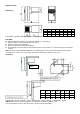
Wall Mounted Units Dimensions 3
Location & Installation 3 to 4
Wall Mount Solo Units Power Absorption Table 4
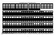
Wall Mount Units Technical Data 5
Access to the Unit Compartment and Evaporator Housing 6
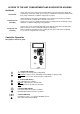
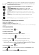
Controller Operation 6 to 7
Controller Parameters Access and Description for Models with Serial Number Ending in A, B, C,
D and E
7 to 9
Parameter List for Models with Serial Number Ending in A, B and E 10
Controller Alarms and Alarm Descriptions for models with Serial Number End Letter from "A"
TO "E"
11
Probe Resistance Values for all Models 11
Fuse Ratings and Wiring Diagram Numbers for Models with Serial Number Ending in A, B and E 11
Wiring Diagram Code Identifications 12
Controller Connections for Controller Kit Part Number 16250204 12
Wiring Diagrams for Models with Serial Number Ending in A, B and E 13 to 18
Parameter Access Instructions for Models with Serial Number Ending in F 19
Parameter List for Models with Serial Number Ending in F 20
Wiring Diagrams for Models with Serial Number Ending in F 21 to 26
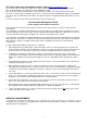
Introduction
It is important to note that all work should be carried out by a competent person.
Solo plus is a range of self contained refrigeration units for small and large coldrooms.
The systems are pre-charged with refrigerant and pre-wired ready for installation into a coldroom with only
electrical connections to be made.
Under certain conditions a drain pipe may be required to drain any excess defrost water to an external source
Basic Description of Operation
Hot gas defrost with crankcase protection
Capillary control
Hot gas vaporisation plus 2 additional electric back up heaters with variable voltage depending on water contact.
Routine Maintenance
In order to keep the unit operating reliably and energy efficient periodical cleaning of the condenser is necessary.
(The frequency being determined by site conditions)
This operation is to be carried out with the unit turned OFF. We advise the use of an air jet blowing from inside to
the outside. If an air jet is not available then use a soft long haired brush on the outside of the condenser taking
care not to damage the fins.
Warning: Condenser fins have sharp edges so care must be taken to avoid injury
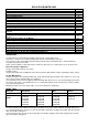
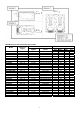
Model Table
Unit Type Refrigerator Meat Freezer
Temp + 10°C +1°C to +4°C 0°C to –2°C -18°C to -21°C
Model
SP101HW
SP201HW
SP301HW
SP401HW
SP501HW
SP601HW
SP101HW
SP201HW
SP301HW
SP401HW
SP501HW
SP601HW
SP101HW
SP201HW
SP301HW
SP401HW
SP501HW
SP601HW
SP101LW
SP201LW
SP301LW
NOTE: Nomenclature “W” refers to Wall Model
As each model operates at different temperatures it will be necessary to set the required operating temperature.
See controller instructions on pages 7 to 9 for models with serial number ending in A, B and E and 19 for models
with serial number ending in F.
See the parameter lists on page 10 for models with serial number ending in A, B and E and page 20 for models
with serial number ending in F.