
Installation guide

1-10 Chapter 1: Installation
SP201-SA™ Customization and Maintenance Guide
3 Save and re-open the configuration.
Communication between the SP201-SA and the control console is
established when you open the saved configuration.
4 Next, type warmstart and press Enter.
The SP201-SA will reboot.
Note: If there is no readout on the control console, communication
with the SP201-SA has not been established. In this case, perform
Step 2 through Step 4 again.
If necessary, unplug the SP201-SA’s power supply and then plug it
in again. If this does not work, contact Technical Support.
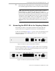
1.5.2 Connecting an External Modem to the SignalPath Device
You may wish to connect an external modem to a SignalPath device so that
you can manage the SignalPath from another location.
Note: You must configure each modem from a terminal (such as a PC using
terminal emulation software). You cannot configure the modem through the
SignalPath. After configuring the modems, connect the remote modem to
the SignalPath.
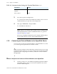
How to Configure and Connect an External Modem to the SignalPath
1 On the local side, use a serial RS232 straight-through female-DB9-to-
male-DB25 cable to connect a local external modem to the control
terminal’s DB9 COM port.
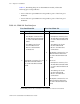
Data bits 8
Stop bit 1
Flow control None
Table 1-2. Communication Settings for Terminal Emulation (2 of 2)
Parameter Value