
Specifications


Connectors 61
Specifications
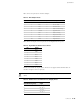
Table 13 lists the pinouts for the DB-9 adapter.
Table 14 lists the RJ-45 connector pinouts for the Gigabit Ethernet ports.
The E1 and T1 PIMs use RJ-48 cables, which are not supplied with the PIM. Table 15
describe the RJ-48 connector pinouts.
Table 13: DB-9 Adapter Pinouts
DB-9 Pin RJ-45 Pin Name I/O Description
1 N/C DCD <– Carrier Detect
23 RxD<–Receive Data
36 TxD–>Transmit Data
4 7 DTR –> Data Terminal Ready
5 4 Ground – Signal Ground
6 2 DSR <– Data Set Ready
78 RTS–>Request To Send
81 CTS<–Clear To Send
9 N/C RING <– Ring Indicator
Table 14: Gigabit Ethernet RJ-45 Connector Pinout
Pin Signal
1
MDI0+
2
MDI0-
3
MDI1+
4
MDI2+
5
MDI2-
6
MDI1-
7
MDI3+
8
MDI3-
CAUTION: To maintain agency approvals, use only properly constructed, shielded
cables.
Table 15: RJ-48 Connector to RJ-48 Connector (Straight) Pinout
RJ-48 Pin (on T1/E1 PIM)
(Data Numbering Form)
Signal
1RX, Ring, –
2RX, Tip, +
4TX, Ring, –
5TX, Tip, +